Here’s the list of the cedar lumber, hardware, and electrical items we bought to build this project:
Wood
4 6″ x 6″ x 12′ for the posts
4 6″ x 6″ x 10′ for the braces
4 2″ x 12″ x 20′ for the girders
14 2″ x 10″ x 18′ for the rafters
14 2″ x 6″ x 20′ for the stringers
With the 7% contractor’s discount the lumberyard generously extended us, the wood cost about $2,700.
Galvanized hardware
35 10″ x 1/2″ lag bolts
7 8″ x 1/2″ lag bolts
1 10″ x 1/2″ lag screw
1 8″ x 1/2″ lag screw
44 nuts
88 washers
Just this hardware alone cost about $500.
Electrical items
1 wet-rated ceiling fan
6 exterior can lights
2 decorative adjustable light switches
1 GFI receptacle
3 exterior electrical boxes
3 box extensions
3 box lids
6 flood lights
100′ of UF cable
a bunch of cable nuts
We got the fan on sale for $129, the lights cost $240, the bulbs were $75, and the rest totaled around $100.
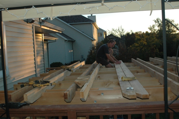
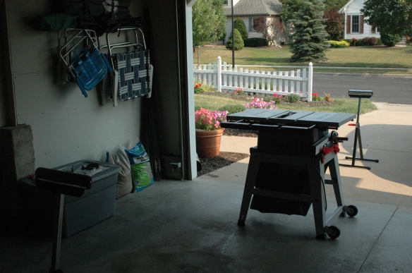
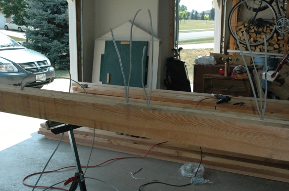
Here’s a photo of the cedar lumber we bought for the pergola after it was delivered and stacked in the garage. This photo doesn’t include the four posts that we’d already planted around the patio.
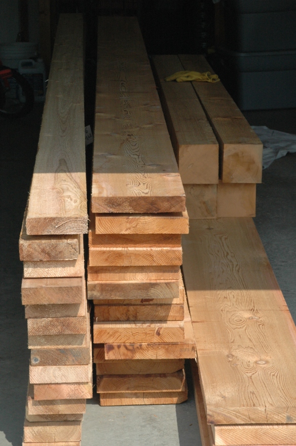
The four boards on the lower left are the girders. They are twenty feet long and rough sawn to 1 ¾ x 11 ¾ and weighed each about 100 pounds. The 6 x 6 posts on top of them are ten feet long, but will be cut into five foot lengths. The eight sections will become the knee braces at each pergola corner. When cut they probably weighed about 45 pounds each. The fourteen boards in the middle will become the rafters. They are eighteen feet long and rough sawn to 1 ¾ x 9 ¾ and weighed about 75 pounds apiece. The fourteen boards on the left are twenty foot lengths of 1 ¾ x 5 ¾ weighing about 45 pounds apiece. They will become the slats that overlay the rafters. The twelve foot 6 x 6 posts I’d already placed in the ground weighed about 110 pounds each, except for one which seemed drier than the other three and weighed maybe 100 pounds.
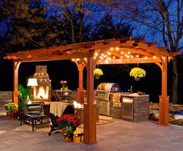
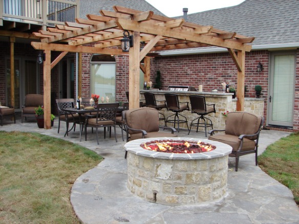
When planning the pergola, we decided we wanted to run electricity throughout to make it more functional for longer periods of the day. Nick wanted to conceal the electrical wiring somehow to give the whole structure a more polished look.
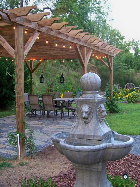
Most examples he looked at that were wired for electricity had cable run through metal or PVC conduit attached to the wood. Some builders forewent the conduit entirely and simply attached their cable to the top, sides, or undersides of their rafters or slats with cable staples. These examples probably were wired after their original construction, as an afterthought. But, as our bedroom overlooks the site of the pergola, he just didn’t want to look down on all his effort to see a bunch of exposed wires or conduit. He was looking for a more elegant way, and knew it had to be part of the plan from the start.
During his research he came across an article suggesting routing a channel along a post and running wire though the wood a couple of feet for a receptacle, concealing the wire and channel with a strip of wood cut to fit snugly. He extrapolated that idea to the entire pergola, and began planning how it could be done.
He started with the post which was going in the ground nearest where electricity runs into the house.
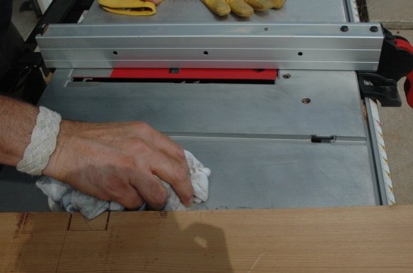
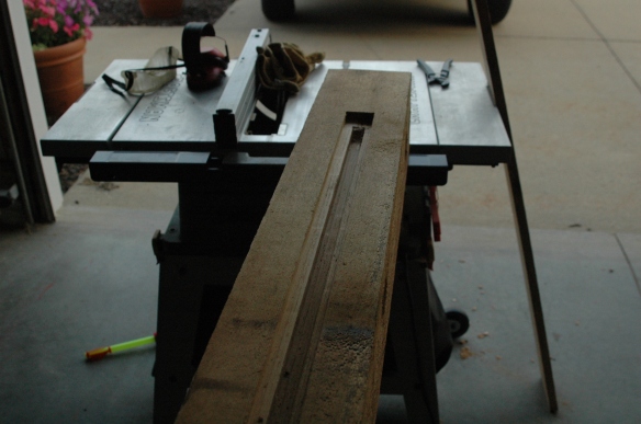
Before beginning the cuts, Nick applied a coating of car wax to make the table surface on the table saw more slippery so that the heavy pieces he would be cutting would slide more easily across.
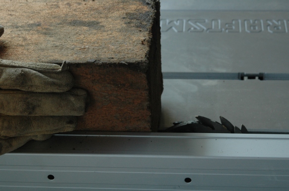
He removed the safety gadgets from the saw. They would prevent the timbers from passing fully over the blade. (The rollers you see below were an indispensible tool.)
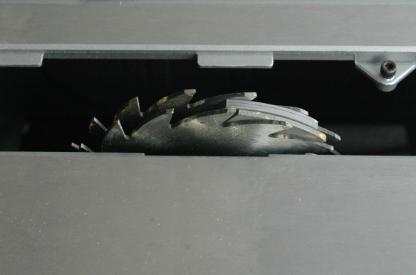
Then he removed the blade and replaced it with ¾” of dado blades.
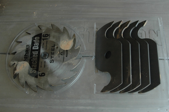
Here are the dado blades installed.
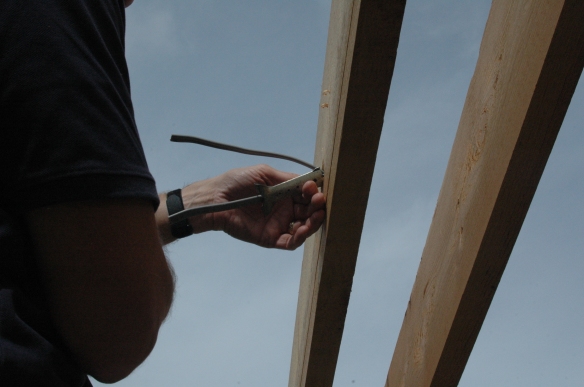
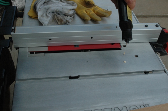
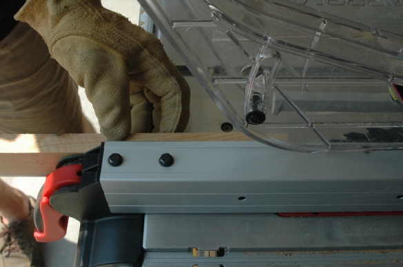
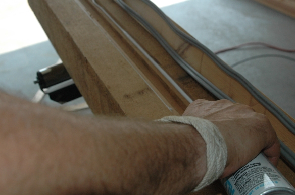
The channel would be cut in the shape of a T, with the deepest part of the cut, where the wires would be placed, being the first pass, and centered on the post. He began the cut at the very bottom of the post.
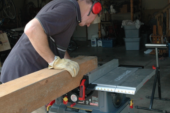
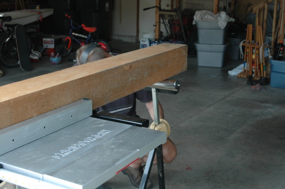
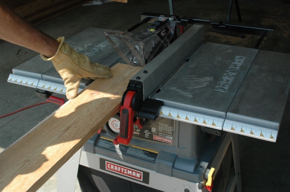
It’s important to align the post with the fence (the guide with the red handle, above), and to ensure the roller supports are perpendicular to the piece being cut so that the wood doesn’t gradually drift out of true and the cut become skewed. Nick checked often during each cut that his work was still flush with the fence, and moved his roller supports several times as the piece was slid along the table, adjusting the height of the supports as needed to keep the post moving along the entire table surface.
Here is the beginning of the very first cut.
Adjusting the height of the rollers ensures an even distribution of the weight of the wood over three points (the table surface and the two rollers) and makes pushing the heavy work over the blade easier, and safer.
He didn’t extend the cut all the way to the top of the post, but only to a point where the terminus of the cut will be concealed by a girder.
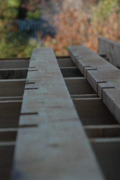
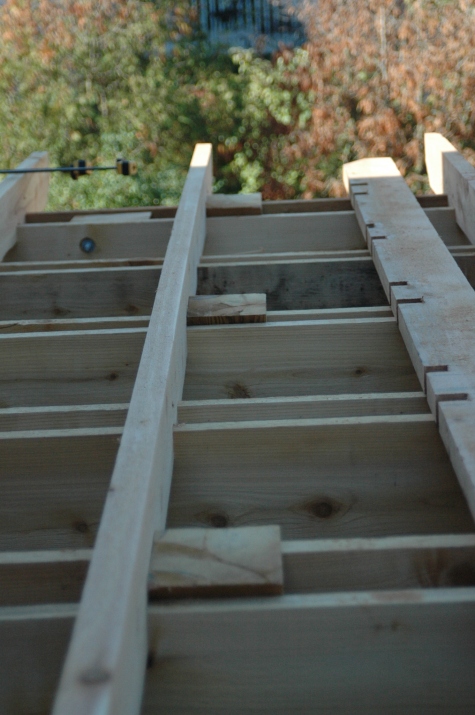
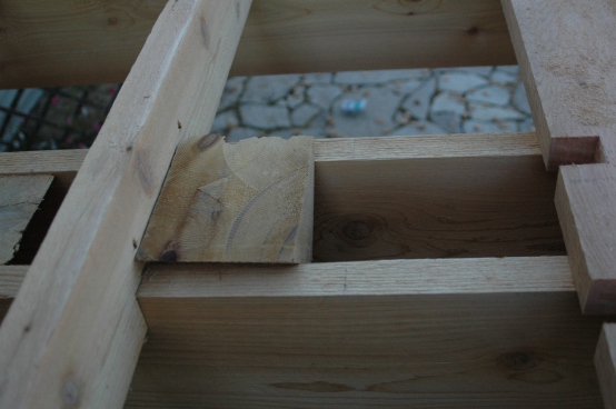
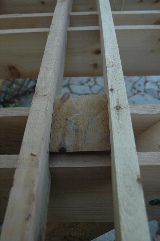
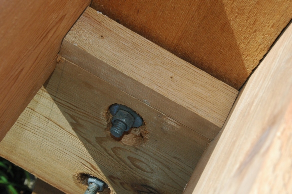
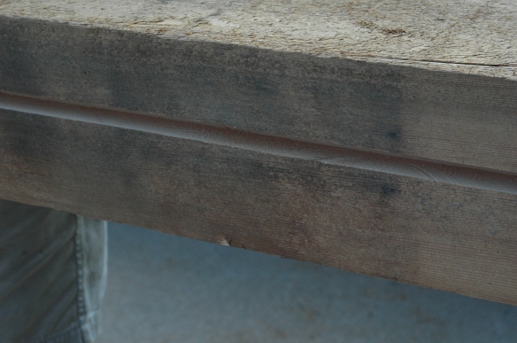
Getting ahead of myself, here is a photo of the girder on the side of the post where the wiring is located. The first pair of rafters is also set, but that happens even later. As you can see, the cut on the post cannot be seen because it ends below the top of the girder. I’ll explain the purpose of the “cap” on top of the girder later. You can see a seam just above the bolt.
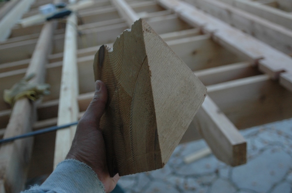
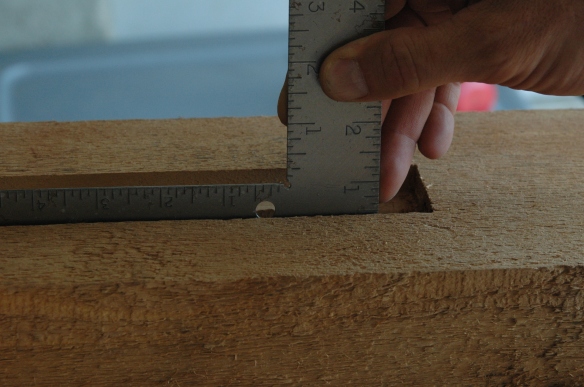
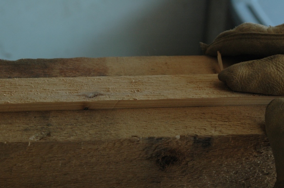
Here is what the post looks like after the first pass.
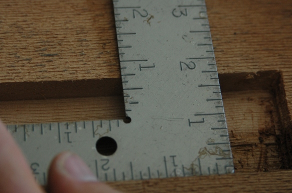
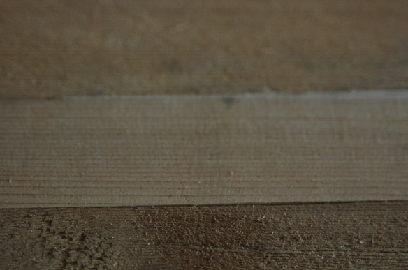
Nick then set the post up as before, moving the fence about ½ inch to create the first half of the top of the T, then moving the fence again for the third pass to complete the T. Here’s what that looks like.
He used a hammer and chisel to square the end of the cut up nicely. Even though the cut would be concealed by a girder, Nick wanted the end of the cut square so that the strip he placed over the entire cut to enclose the wire would fit snugly at the top which, with a little silicone caulk, would prevent rainwater from running down the channel.
The dimensions of the cut were 1” deep and ¾” wide at the bottom of the T, ½” deep for the cross part of the T, and 1 ¾” across the top of the T.
Next, having replaced the dado blades with the table saw blade, he reattached the safety attachments to the saw and began cutting what would be the cover of the groove, first ripping it for width,
then for depth.
Then he dry-fitted the cover to ensure it was snug.
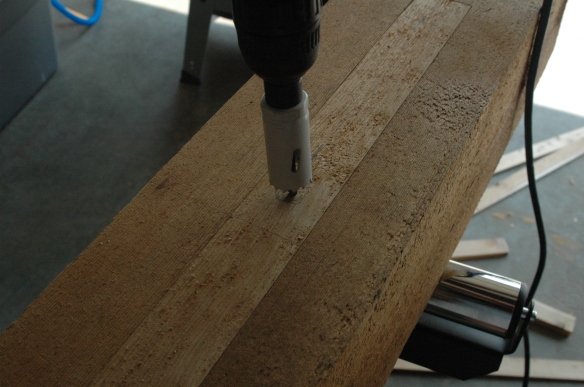
Next he determined where he wanted the wires for the receptacle and switches to protrude from the post, marked the locations, and used a 1” hole saw to take care of business. The hole he’s drilling here is the one at the top of the post, where the fan and light cables will emerge. The cover is not yet attached.
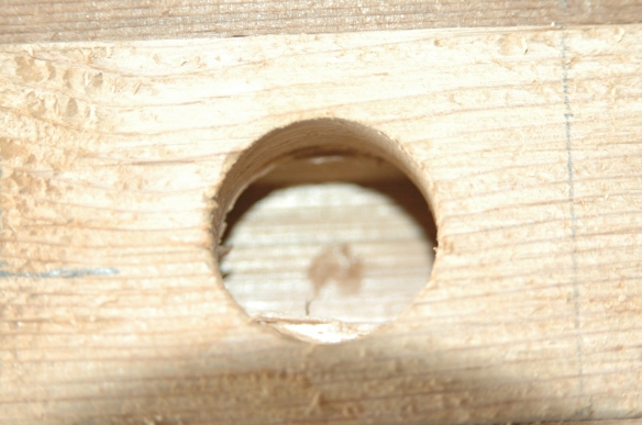
Here’s what the lower three of the four holes look like when done. The bottom one is for the receptacle, and the middle two are for the fan and light switches.
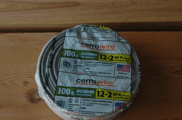
Next he removed the cover and began laying wire. He used UF 12-2, pretty heavy gauge stuff, and designed to be buried. That’s what the UF means, underground feed. The cover is really sturdy, and a pain to strip. He could have used thinner gauge wire, but he had nightmares of having to disassemble the entire pergola if he had and something snapped while he was working it through a bunch of 90 degree bends. Better safe than sorry.
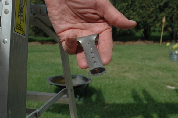
Here’s what the UF wire looks like. It’s got a very tough grey cover, impervious to the elements.
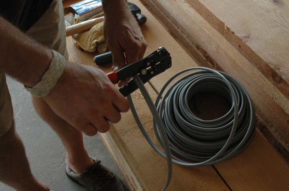
We bought this wire cutting and stripping tool several years ago when he finished our basement. It’s very handy.
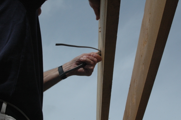
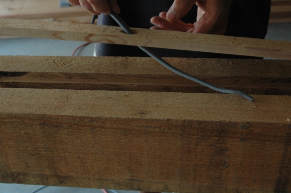
From the bottom of the post he ran up the single cable which would bring power from the house, and fed it through the receptacle hole.
From that hole he then fed two wires and laid them further up the groove to the two switch holes.
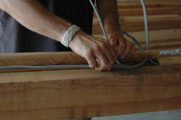
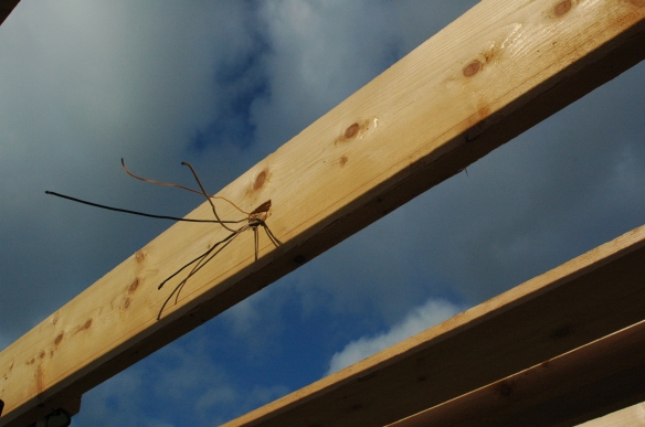
Lastly, he fed one cable each from the switch holes and continued them up the groove to the fourth hole he drilled near the top. Here’s what that looked like after he’d run the first of these two cables.
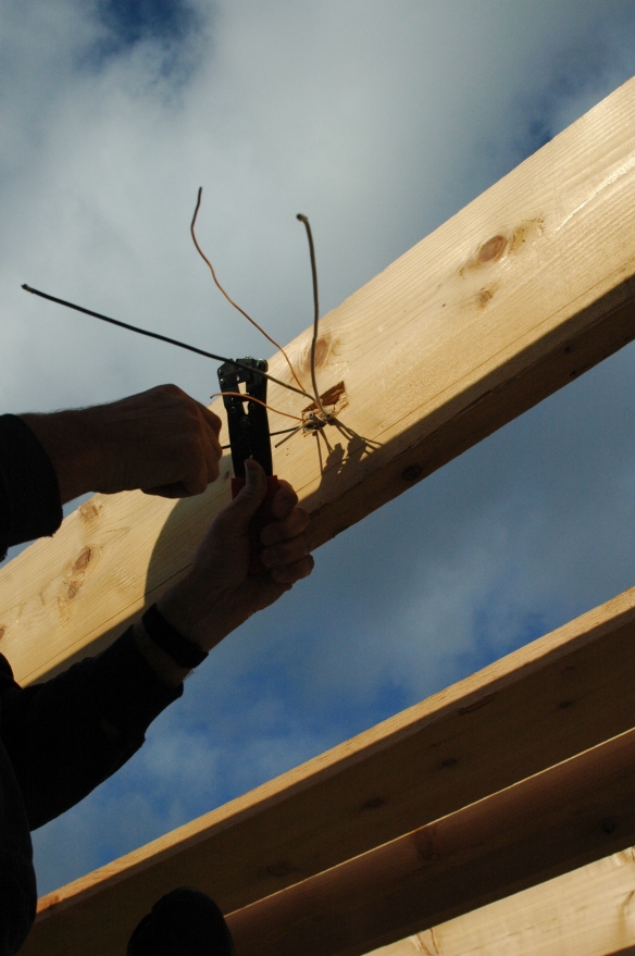
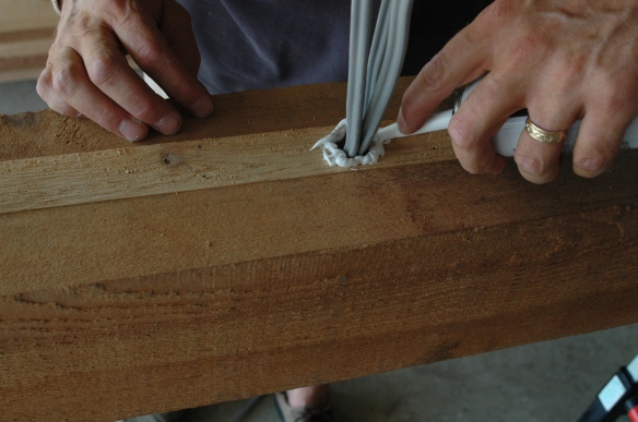
Then Nick laid down a bead of silicone caulk on both sides and the very top of the cut, near the top of the post,
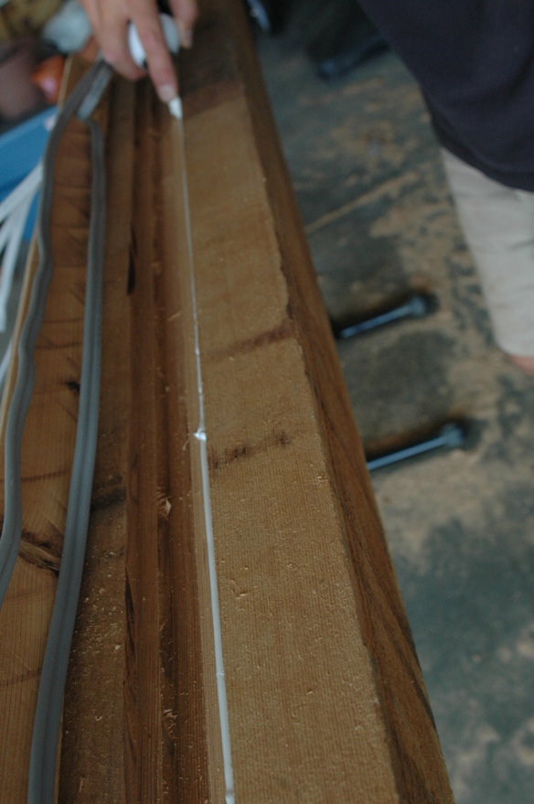
and reinserted the cover into the channel, very carefully nailing the cover down with finishing nails, angling the nails away from the wire to minimize the possibility that he might nick one.
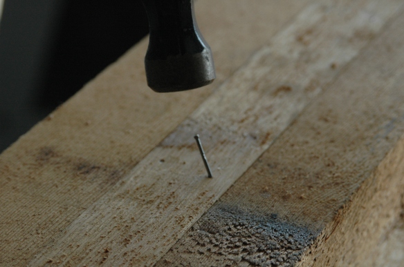
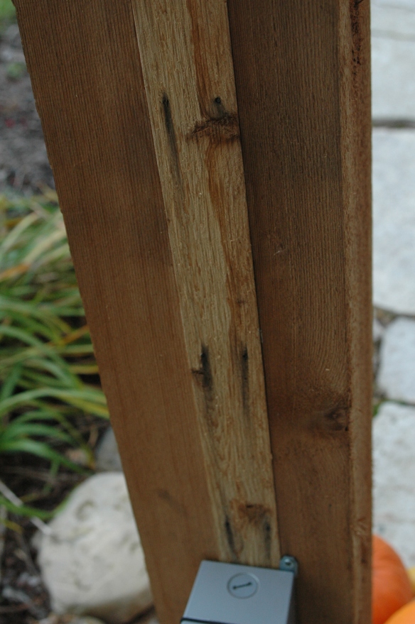
He didn’t think to use galvanized finishing nails, which isn’t a big deal, but still a regret , because after we’d set this post in the ground, the first rain it was exposed to caused the nail heads to begin discoloring the cedar below them in streaks. Thankfully the wired side of the post faces the house and it’s not really noticeable, but the post looks like it’s got two dozen tiny little eyes, all with running mascara. Nick made sure that every bit of hardware from then on was galvanized.
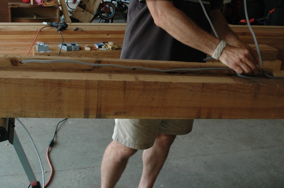
He left about fifteen feet of cable leading from the receptacle, which was used to connect the pergola to the breaker box in the basement. Here it’s resting on a board that’s not a part of this project.
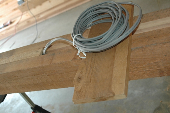
There were five feet extra after it was connected, but that’s a good thing. Cable is cheap, but rewiring the post if he came up short would have been a major headache.
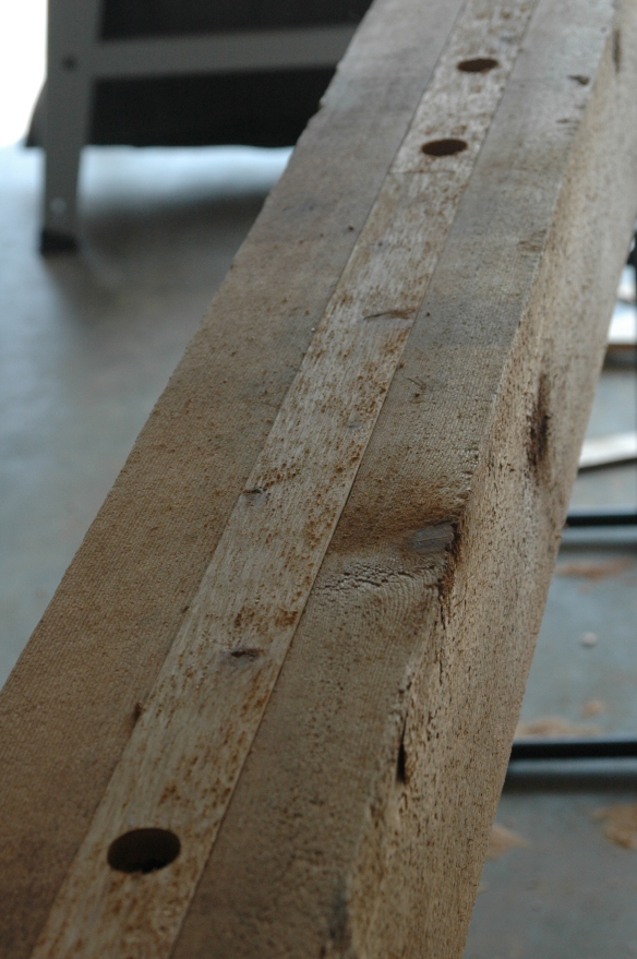
Here’s what the post looks like after these steps. The wires on the right will be in the receptacle box. The cables coming out of the post near the center are for the light and fan switches, and the cables emerging at the left are for the lights and fan themselves. He left about ten feet to reach the first light, and about twenty for the fan.
Next he placed a thick bead of caulk around the holes for the receptacle and two switches to seal the holes against the elements,
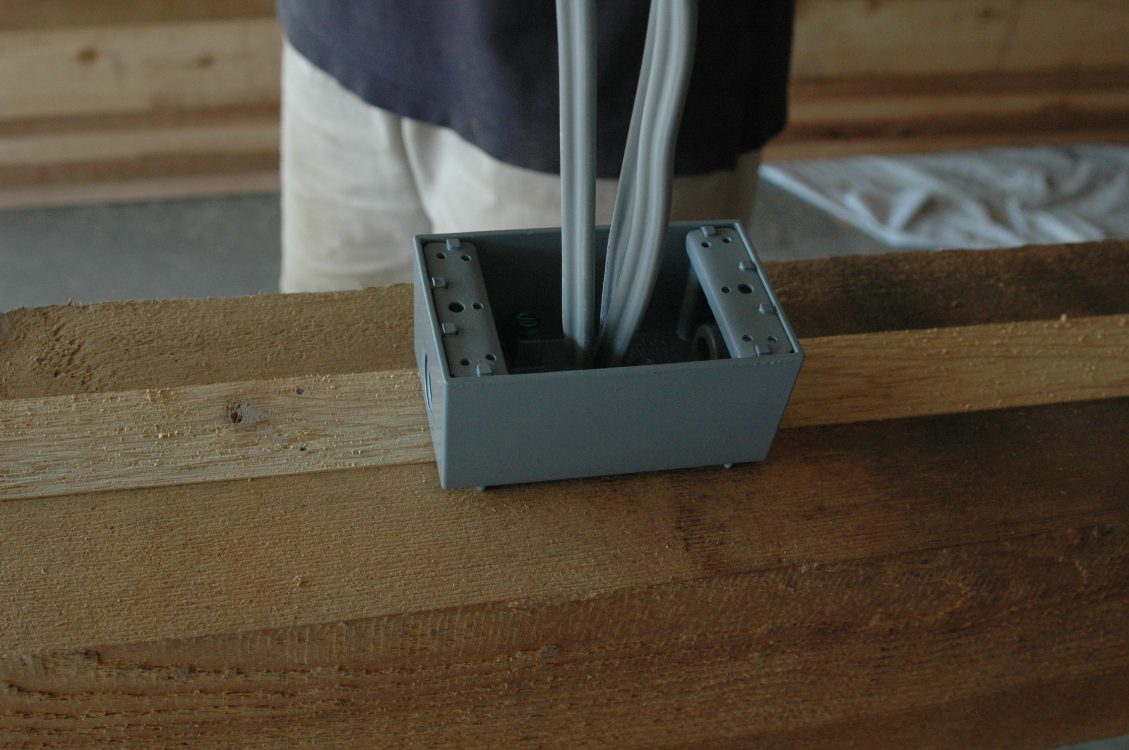
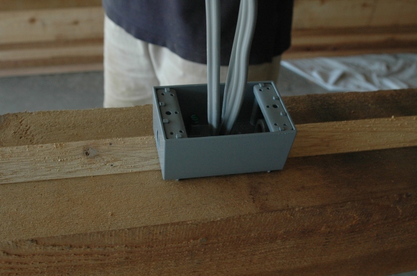
and placed the outlet boxes in position, pressing them against the caulk and screwing them down. Here’s the receptacle box. The two switch boxes are just like it. He drilled a weep hole on the bottom of these boxes to prevent rainwater from collecting inside them.
Voila! Post done! Next step, sticking it in the ground.