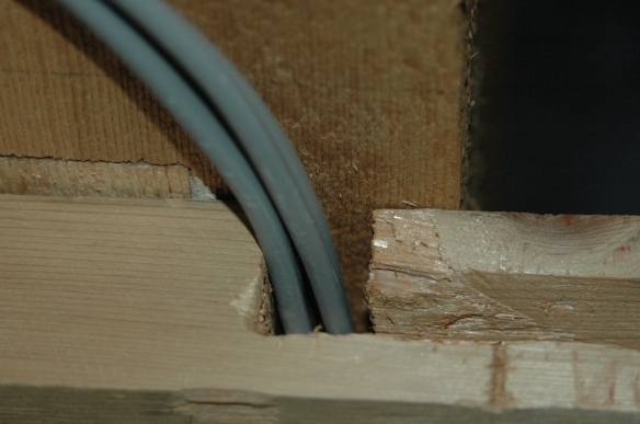
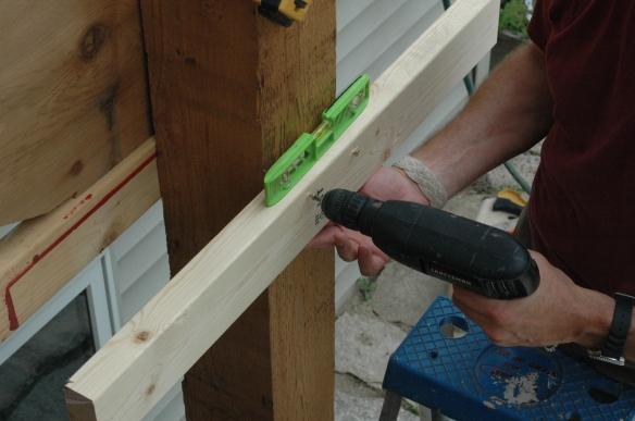
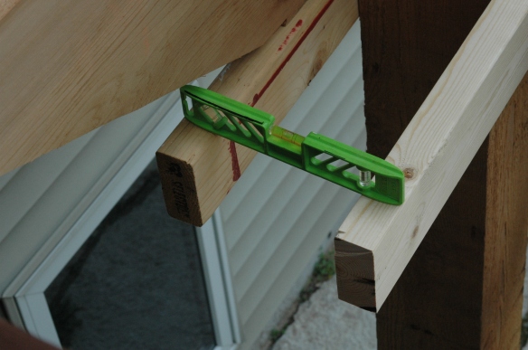
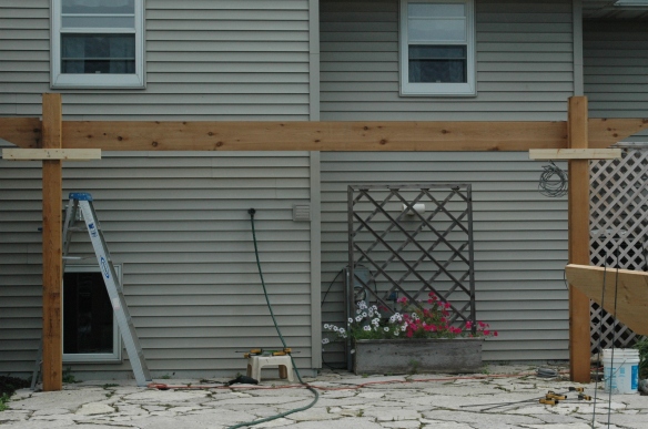
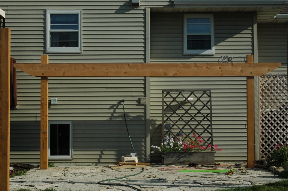
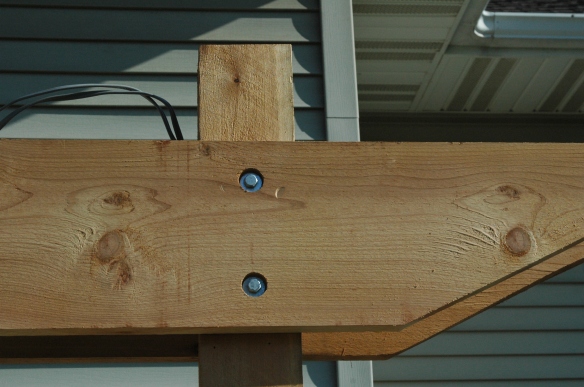
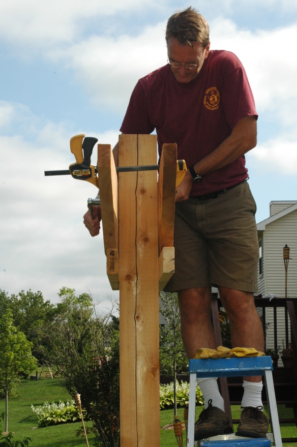
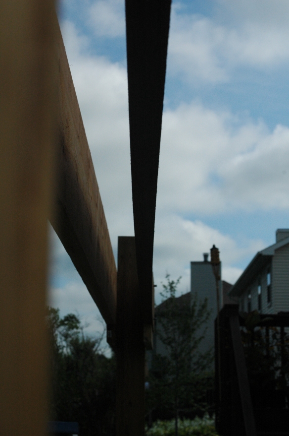
Attaching the Slats

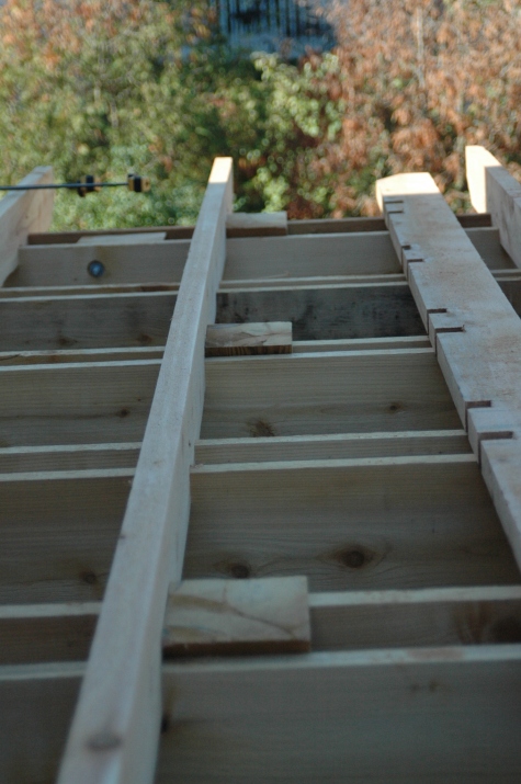
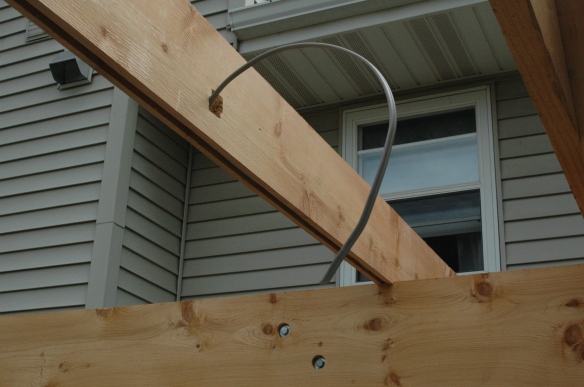
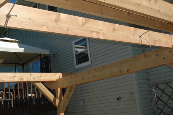
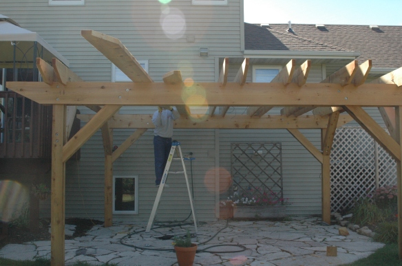
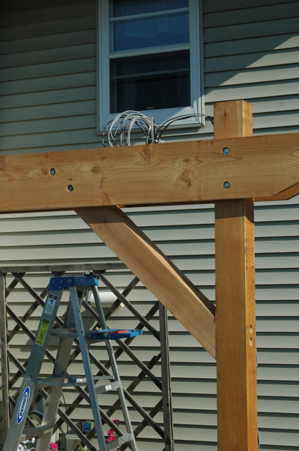
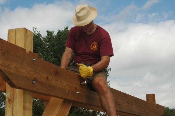
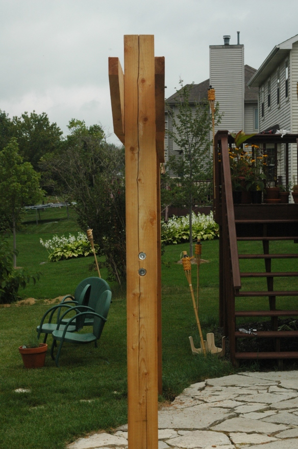
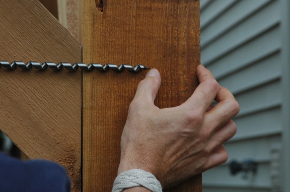
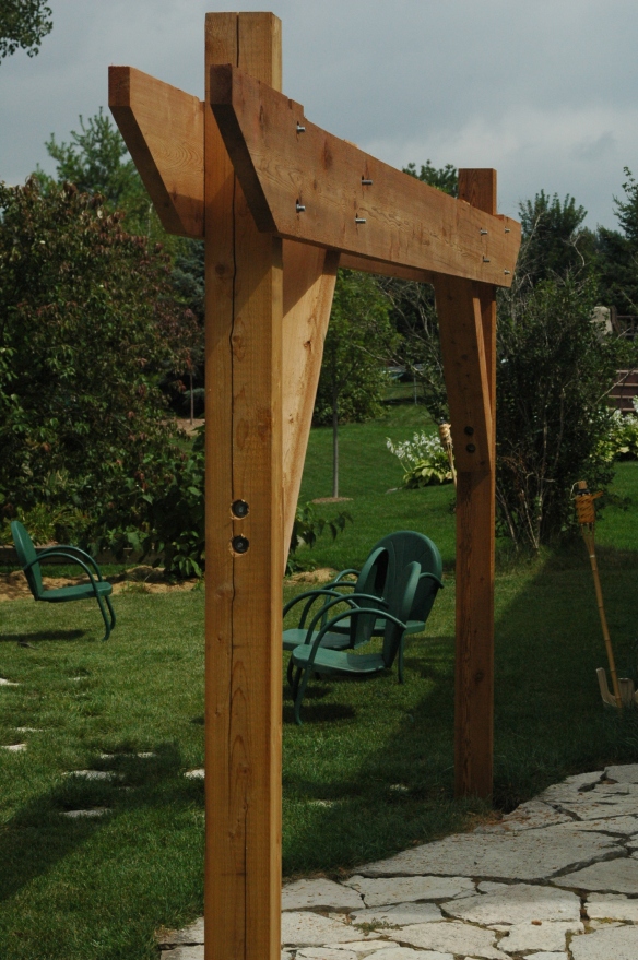
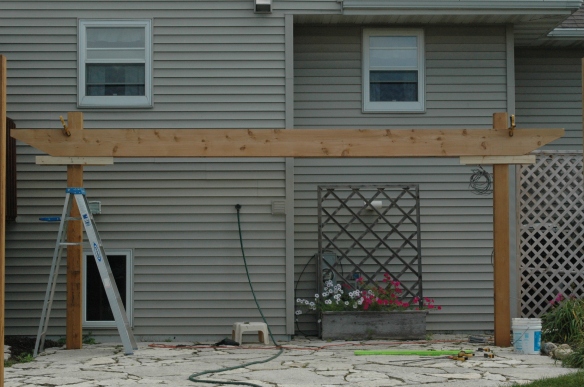
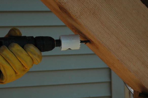
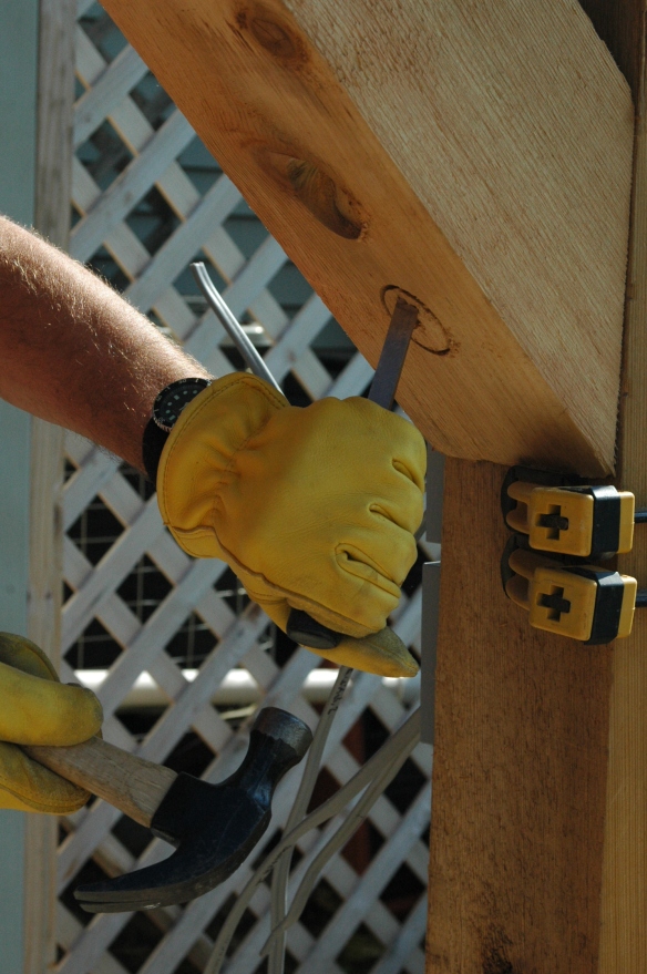
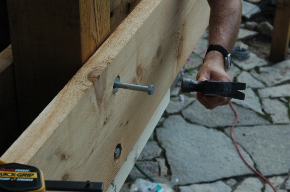
All the really hard work had been done by this point.  From here on out what remained, after cutting the slat ends to match the rafters and girders, was simply the tedium of measuring and marking and sawing and chiseling each of the notches in each slat, fourteen notches per slat, fourteen slats.  That’s a total of 196 notches that needed cutting.

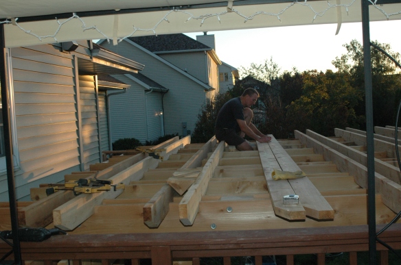
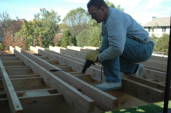
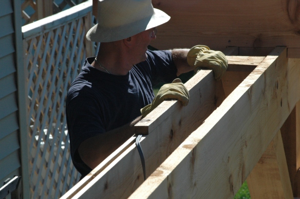
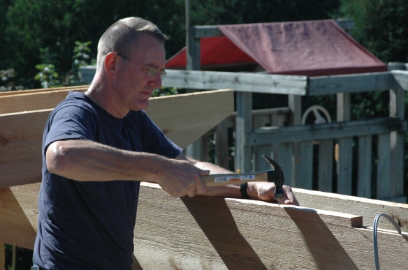
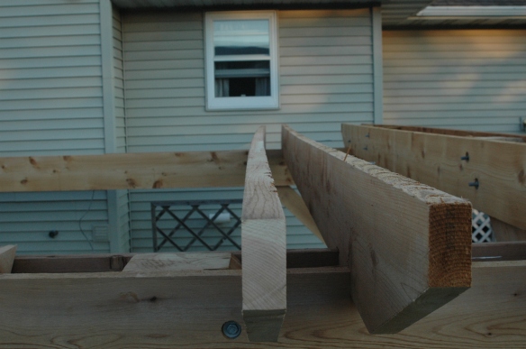
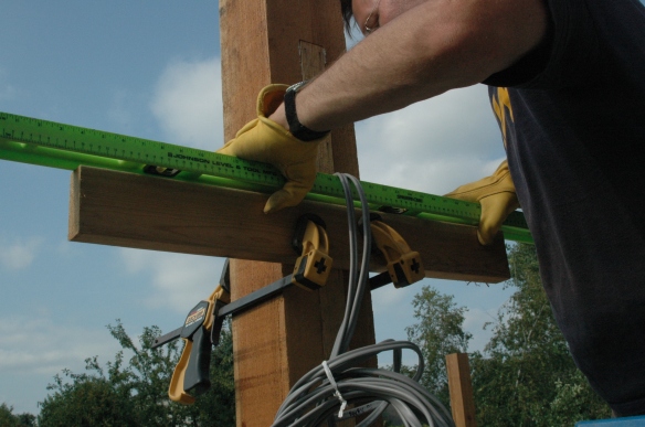
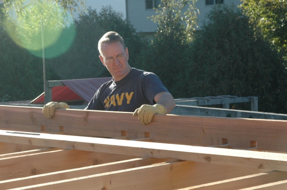
Here Nick is mounting the first of the slats.  If you look closely you can see that the depth of each of the notches is about the same.  That worked out all right as, where the rafters were attached to the girders the tops of all the rafters were all about level.

DSC_1072

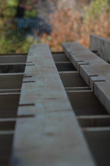
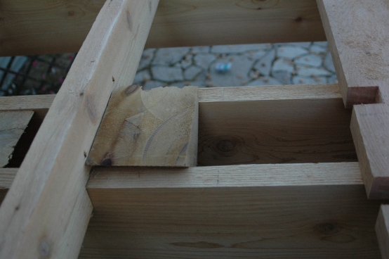
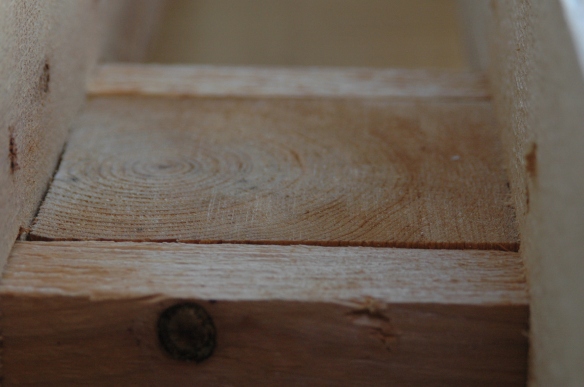
Toward the middle of the rafters, however, due to the imperfections in the lumber that we’ve written about before, the slat notches varied considerably in depth.  Nick wanted the notch to meet up with the top of the rafters as closely as possible.  He was able to do this by first laying the slat flat across the rafters, then eyeballing (estimating) how high above or below a level line from the first to the last rafter each of the middle twelve rafters rose or fell because of a crook.  Then he increased the depth of the notch for rafters that crooked above the mean and decreased the depth for those rafters that fell below the mean.  What we ended with was a wide variation in notch depth.

DSC_1126


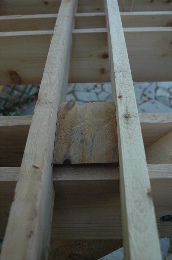
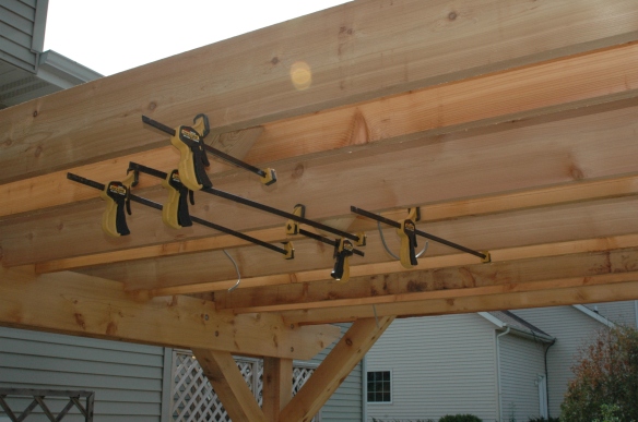
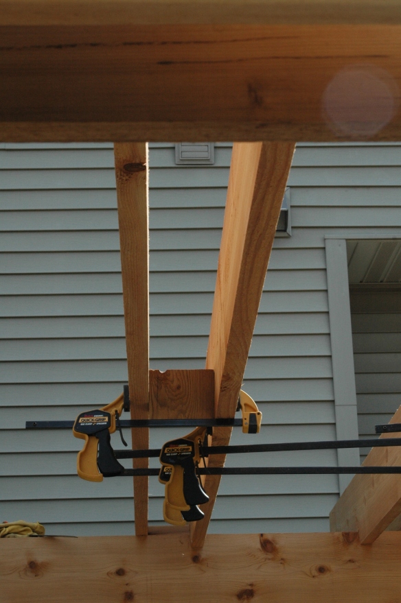
The distance between each slat in a pair needed to match the distance between each rafter in a pair, so Nick used the same 5 ¾” wide blocks for this step that he’d used previously.

DSC_1127


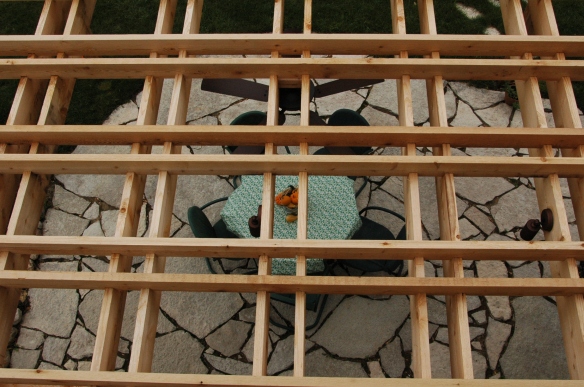
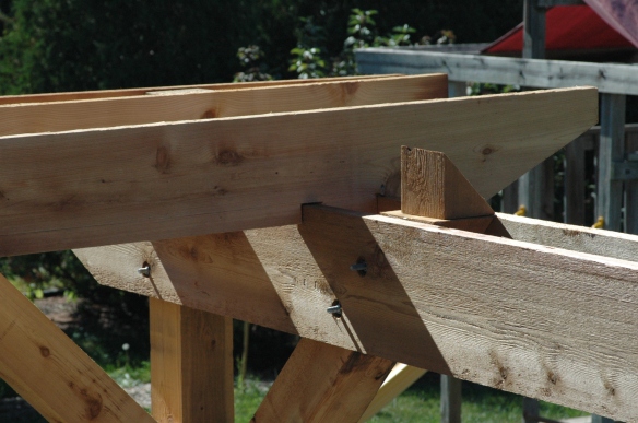
Though the distance between the pairs of slats was less than the distance between the pairs of rafters, because we were fitting fourteen slats into a 14’ span, and an equal number of rafters into a 16’ span, because the boards in each pair of rafters and slats were all 5 ¾” apart, the intersections of the pairs of slats and pairs of rafters produced perfect squares when looked at from above or below.

DSC_1203


Nick used three spacer blocks to ensure a uniform distance between the slats in each pair.

DSC_1130

DSC_1129

DSC_1128

DSC_1124


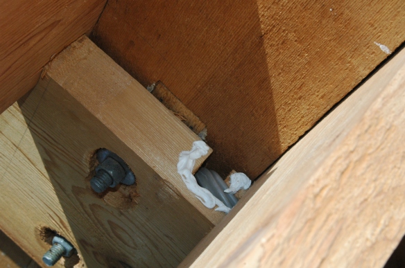
Here Nick is drilling the last galvanized deck screw of the project.  The only things left to do were to apply some silicone caulk to the places where rain might get into the light fixtures and fan, and wire the switches and receptacle.

DSC_1133


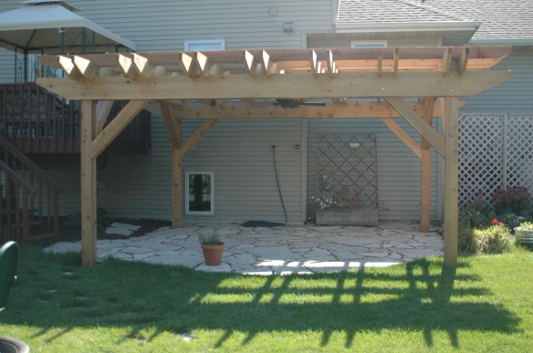
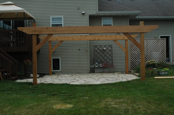
Now, for the finished project…

DSC_1137


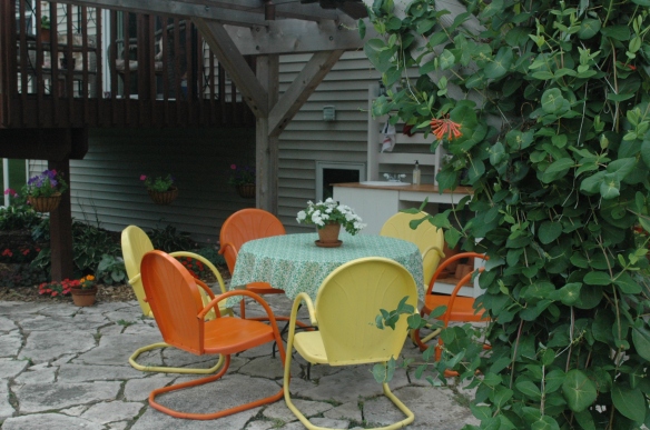
And how it looks almost 2 years later.

DSC_0464


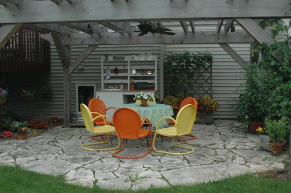
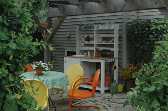
In the background you can see the potting table that we made out of reclaimed pallet wood.

DSC_0459


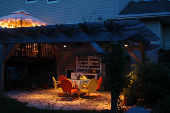
And a night shot.

p8


This is , without a doubt, our favorite place to be as soon as the weather in Wisconsin is even remotely close to warm.

DSC_0463


Phase 2 will be an outdoor fireplace to the right of the patio, where the kitchen garden is now.  We’ve collected some bricks from an old school house that, sadly, burned down a few years ago. The city has given us the go ahead. Now we just have to motivate ourselves to begin.

Hope this helped anyone who is considering or in the middle of tackling a project like this. It’s definitely worth the time and energy!

https://cdncache-a.akamaihd.net/store/

Attaching the Lights and Fan

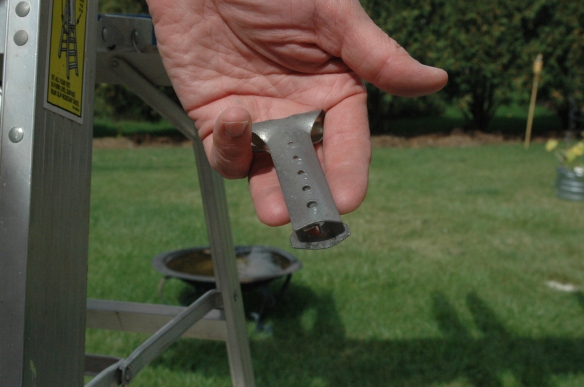
After rough wiring the pergola, the next step was to attach the light fixtures and fan.  When Nick finished our basement he acquired a number of handy tools that might or might not ever be used again.  Here’s a picture of a tool that’s been used several times since.  It’s used to make a slice along a length of electric cable, like the UF cable Nick used to wire this project.  We think it’s called a ripper, and if any of our readers are Australian, that’s exactly what we think of it.

DSC_1010


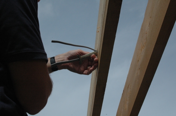
Here Nick runs a cable through the ripper.  Notice that he had previously cut the UF cable down from their longer lengths to the approximate length that would fit in the light fixture.

DSC_1011


You’ve got to get a real grip on the ripper when pulling it down the stretch of cable, but even though Nick had had experience with this tool he seemed to get bit by it time and again when he got to the end of the cable and the halves of the ripper snapped together.  Nasty little blood blisters galore.  Here’s a tip: wear gloves.

DSC_1012


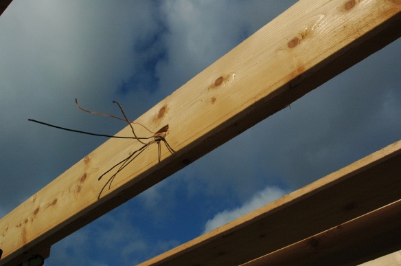
Here are several wires stripped of their cable coverings.

DSC_1014


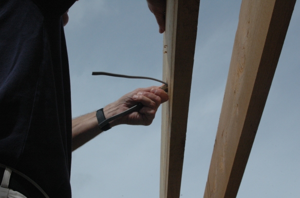
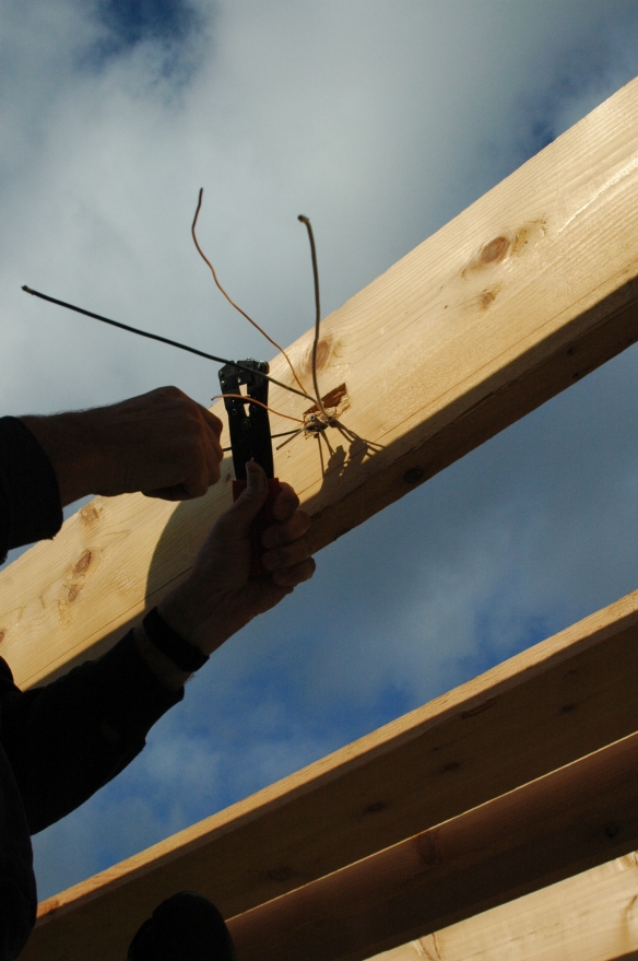
Here Nick is using another tool acquired for the basement project to further cut the wires to length.

DSC_1019


There’s a wire stripper feature to the wire cutter in the photo above, but the non-ground wires in the UF cable, in addition to their black and white insulation, have another layer of clear plastic over them that proved too slippery for the wire stripper.  The stripper would separate the insulation from the end ½” of the wire, but couldn’t bite through the clear plastic casing.  Nick remedied that be scoring the plastic with his knife, then using the stripper he removed the end ½”.

DSC_1023

Here’s what the wires look like prepped to attach the lights.

DSC_1025

From some of the wires he’d shortened Nick took lengths of ground wire and using a needle nosed pliers put a couple of curves in them for attaching to each light fixture.

DSC_1026DSC_1027

DSC_1030

Using a carpenter square Nick made sure each light fixture was 2” up from the bottom of each rafter,

DSC_1036

he marked where each screw was to be drilled,

DSC_1037

DSC_1038

and attached the base plate of each light.

DSC_1041

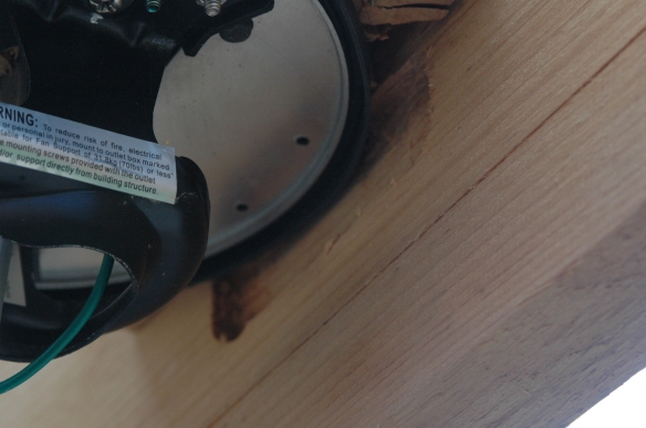
If you’re a professional electrician, or even just a handyman who does a lot of wiring, the problem with the setup in the photo above will jump out at you.  Later, when the lights and fan were all attached, Nick had a friend who owns an electrical contracting business come over to attach the feeder cable from the wired post to the circuit box in the basement.  Nick explained to him how he’d mounted the lights, and after Nick had explained the process, and after his friend had complimented his wiring plan and execution, the professional suggested that we should have nevertheless made the base of the lights fire-resistant by having some sort of metal plate between the rafter and the light base plate.  What Nick did was leave wood exposed to any arcing that might occur if his connections should ever fail.

So, we’ll explain the correction Nick made a little later in this post.  The attachment of the lights explained in this post is still good, though. ** Just be sure before you build your own pergola with lights that you read all the way to the bottom where we explain the right way to enclose the light bases.**

So here Nick is shortening the wires that are part of the fixtures.

DSC_1042

And stripping them.

DSC_1043

Using waterproof silicone filled nuts Nick wired the lights.  Have a rag handy.  The silicone gets messy really fast.

DSC_1045

Then bending the wires to fit the spaceDSC_1049

Nick attached the covers.

DSC_1050

And here’s the (nearly) finished installation.  Notice how the strip of wood that Nick removed to install the cables, then re-attached, is barely noticeable.

DSC_1054

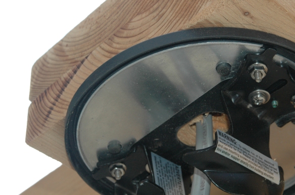
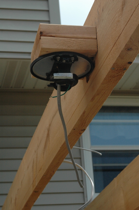
Next came the fan.  As you can see from the following photograph the mounting bracket came with an integral metal plate, so this fixture was good to go when installed the first time.

Using a couple of ladders and several pieces of waste wood to support the fan hub, Nick wired the fan.  This photograph clearly illustrates the overhang of the base that was necessary because the fan base exceeded the space Nick wanted to maintain between the rafters, and later the slats, throughout the project.  Remember that he had routed depressions in rafters 7 and 8 to accommodate the extra width of the fan base.


DSC_1057

DSC_1055

Here’s the fan all wired up.  Notice the hole in the base cover at the bottom of the photo.  There are two holes through which the mounting screws are set into the base.  We selected a nice wet-rated Hunter Fan.  The only complaint I have with it was that the fan only comes with two mounting screws.  What’s the cost of a third screw?  The photo after this shows the cost of not having a third screw.

DSC_1059

By the time we were finishing this project August had turned to mid-October and Nick’s fingers were getting a little stiff.  When he was aligning one of the two screws with its hole it slipped out of his fingers, falling to the patio below, which is made of flagstones of extremely irregular surface.  The screw, being light, bounced unpredictably.  In the end, when it was found, we discovered it had bounced about ten feet.  It took Nick and three of our kids about 45 minutes to cover just about every square inch of our patio looking for that screw.  So that was the cost of not having a third screw.  Nick would gladly have paid another few bucks for a fan with an extra mounting screw if he could have avoided this waste of time.

DSC_1060

Here’s the fan ready for the blades.

DSC_1062

Nick, attaching the blades.  Note how close the top of the fan hub comes to the bottom of the rafters.  To be within code the fan blades had to be 7’ 2” from the patio.  That’s the reason we had to recess the fan base.  With the recess the blades met code.  When designing the pergola we wanted the top of the slats that lay across the rafters to be below the level of a kitchen window that overlooks the back yard.  If that limitation had not been part of the design process we could have made the entire pergola six inches taller and simply mounted the fan to mounting blocks attached to the underside of the rafters.  But I like how Nick did this.

DSC_1064

OK, back to the light fixtures and the steps necessary to make them safe.  Here’s a metal electrical junction box cover.  It’s the same diameter as the light bases that are screwed to the rafters.  Nick had to drill three holes through these covers, one to let the screw that mounts the light cover to the base through, one to let the screw that attaches the ground wire to the base through, and the largest hole to let the incoming and outgoing wires through.  The last light on the circuit only has incoming wires, though.

DSC_1146

This is a drill bit designed to go through metal.  As you can see, it’s stepped, with diameter indicated for each step.  These are expensive.  Nick spend about $35 for this bit, but it was the only tool for the job.

DSC_1148

The plate clamped to a work surface.

DSC_1150

Drill bit at the ready.

DSC_1151

Nick had marked the location of each hole using a light base as a template, and having determined the necessary diameter for each of the three holes, began to drill.

DSC_1153

The first hole was for the mounting screw.

DSC_1155

The second was for the ground wire screw.

DSC_1156

The last hole was for the wires, and had to be wide enough for the clamps Nick used to ensure a snug and safe passage for the wires through the sharp holes.

DSC_1157

DSC_1158

DSC_1160

DSC_1159

Nick removed each of the lights, then passed the wires through the plates, clamping them in.

DSC_1164

Here Nick has re-affixed the base plate to the rafter.  The wiring is no longer exposed to wood.

DSC_1165

Attaching the lights proceeded exactly as described earlier in the post.


Next post: Attaching the slats.

Pergola Post VII: Setting the Rafters, Part 2

The first four rafters have been mounted to the posts, and of the remaining ten three required special handling, which we explained in the prior post. Now Nick was ready to begin wiring those three rafters and mounting them with the rest.

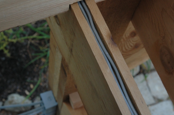
Remember the cables emerging from the wired post need to be set into the groove that had been cut in the first girder. Nick had laid the cables into the groove prior to mounting the second rafter. Here’s a photo of how that looks. He put some silicone caulk around the groove between the rafters to prevent water from getting into the channel from that point.

DSC_0951

Here Nick has placed the 6” cap over the girder between the rafters and nailed it down. Later he would caulk the ends and post side of the cap for watertightness.

DSC_0952

Here the fan and light cables continue in the groove from under the second rafter.

DSC_0980

Remember that Nick had removed a strip from the top of the first and third girder to serve as a cover for the wires set in their respective grooves. As the wired rafters were set, Nick cut these strips into smaller pieces to cover the girder grooves as he progressed. In this photograph Nick is checking the fit of the girder cover from the second to the third rafter. Next he’ll carefully nail the cover down, with galvanized nails. The wire that is lying outside the groove will be going to the first light, which is on the third rafter. The fan cable is still lying in the groove. In Patio Pergola Part II we wrote that Nick left about ten feet of cable to run to the first light and twenty feet to run to the fan from where the cables exited the post.

DSC_0993

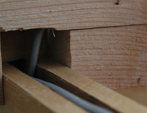
Here the third rafter has been set on the girders and the light cable had been fed up into the groove on the bottom of the rafter. Using deck screws fed into pre-drilled pilot holes to avoid splitting, the 6” cap has been reattached to the rafter, between the first and second girders, after the cable was fed into the rafter groove. Behind the cables is the butt end of the cover that Nick is fitting in the photograph above, which extends about ½” beneath the rafter. The fan cable continues on in the girder groove. The second section of groove cover will also slide about ½” into the cavity from where the light cable enters the rafter.

DSC_0984

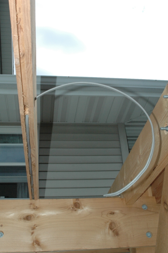
Here are two photographs of the light cable fed through the rafter groove and emerging from the chamber of the first light fixture.

DSC_0982

DSC_0981

Next Nick ran a section of cable from the first light location to the second, and then from the second location a length of cable sufficient to reach the third light, which will be located on the seventh rafter. You can see that the incoming cables enter the first hole we wrote about at the end of the prior post, while the outgoing cables exit from the second. Nick made certain to leave enough cable emerging from the rafter to wire the light fixtures. That’s kind of important.

DSC_0986

In this photograph the groove cover was reattached to the bottom of the rafter, again with deck screws set in pilot holes. There’s not much room for error here. The rafter is 1 ¾” wide, and the groove is ½” wide, leaving only 5/8” on either side of the groove to take a screw, preferably closer to the edge than the middle. Nick clamped the strip on and then drilled the pilot holes and then removed the strip to check that the holes were a safe distance from the wires.  Nicking the wires is something to definitely be avoided.Setting rafters 7

The cable from the second light exits the third rafter and enters the third girder the same way it entered the rafter from the first girder, snaking from one groove to the other. Here Nick is nailing the cover running from the third to the seventh rafter. He had previously attached the section of the third girder groove cover from the second to the third rafter. At the end of this section of girder cover the cable will bend up and enter the seventh rafter.

The non-wired rafters, numbers four, five, six, eight, nine, ten, and twelve simply sit on top of the girder covers. There was no need to segment the covers further as the only reason for splitting the covers was to permit a wire to pass from girder to rafter or rafter to girder.

Nick used deck screws to reattach the covers on the bottom of the rafters because those covers are hanging from the rafters, but he used galvanized nails to reattach the covers to the girders because they are simply resting on the top.

DSC_0991

Here is the third rafter completely installed, with covers reattached to both rafter and girder. The seam between the covers and the rafter and girder can just barely be seen. When the electrician who connected the wired post to the circuit box looked at the lights and fan with no apparent wiring to deliver power he was impressed. That made Nick feel pretty good.

Setting rafters 8

The seventh rafter was prepared just like the third, except that on the side of the board opposite the lights, at the center, a single hole was drilled up from the groove, and a cavity to pass the fan cable through was chiseled. The eleventh rafter was prepared and wired like the third, except, as mentioned previously, no second hole was needed for the sixth light.

Jane wanted the rafters, and later the slats above them, to form a sort of checkerboard pattern. Getting ahead of ourselves as we’ve done several times already, here’s how that turned out.

DSC_1203

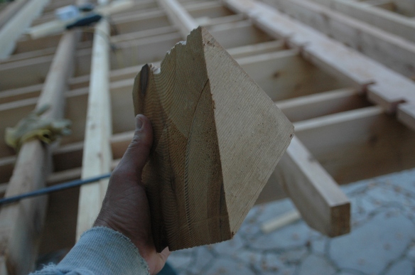
The rafters and slats had to be a consistent distance apart. To get a uniform distance between the two boards that comprised each pair of rafters and slats, Nick used a piece of scrap from the angle cut at the end of a brace as a spacer. That’s the chunk of wood resting on the top of the brace two photos above. The space between the boards comprising the pairs of rafters and slats is the same, therefore, as the space between the first and second rafters, and the thirteenth and fourteenth, which sandwich 6” x 6” posts, which are actually 5 ¾” square.

Some algebra was necessary to determine the spacing between the pairs themselves. Now when ever any of our kids complain about math class and say, “When will I ever use this stuff in the real world?”, we just point out the window!    As you will recall, the dimensions of the pergola, without considering the cantilevering overhangs of the girders, rafters, or later slats, is 14′ x 16′. Starting with the 16′ length for the rafter spacing calculation, the distance from the outside of the first rafter to the outside of the fourteenth is the sum of the distance from the outside of the posts, 16′, plus the combined thickness of the two rafters, 3 1/2″, or 16′ 3 1/2″. There are seven pairs of rafters, and six spaces between these seven pairs. So the equation is:

7x + 6y = 16′ 3 1/2″

We know that x represents the width of a pair of rafters, which is the distance between them, 5 3/4″ plus the combined thickness of the boards of the pair, 3 1/2″, for a total of 9 1/4″. Y is the distance between the pairs, which is what we’re trying to determine.

Converting 16′ 3 1/2″ to inches we get 195 1/2″. So

7(9 1/4″) + 6y = 195 1/2″
65 3/4″ + 6y = 195 1/2″
6y = 195 1/2″ – 65 3/4″
6y = 129 3/4″
y = (129 3/4″)/6
y = 21 5/8″

The distance between each pair of rafters and the next pair was 21 5/8″. Using the same math later for the slats, and the 14′ length, the distance between pairs of slats was 17 5/8″. These distances give the nice checkerboard pattern above.

Nick had to work with pieces of lumber that were imperfect. Here’s one of our rafters.

DSC_0995

When pieces like this were mounted they retained their curve.

Setting rafters 9

By using a bunch of clamps, however, Nick was able to straighten these rafters before they were screwed down to the girders. Screwing them down once they were clamped straight forced them to stay straight, or much straighter than they were. When Nick set the slats later, their 1 ½” notches further held the rafters true.

Setting rafters 14

DSC_1003

At this point Nick bought a Hunter wet-rated ceiling fan. The base of the fan was 6 1/2” in diameter. This posed a problem, as the spacer Nick had been using was 5 ¾” wide, consistent with the dimension of the four posts. He considered his options, the first of which was to simply make the space between the seventh and eighth rafter wide enough to accommodate the fan base. You’d be surprised, maybe, how noticeable a 3/4” deviation from the norm can be. As Nick said, that option was a non-starter.

Nick got out his router again. On the insides of the seventh and eighth rafters, prior to screwing them down, he routed a 4” x ¾” depression ¼” and 1/2″ deep, respectively, in the center of each, just below where the fan cable would emerge from the chiseled-out cavity in the seventh rafter.

Then, from a length of 2” x 6” cedar Nick cut two pieces measuring 5 ¾” x 5 ½” x 1 ½”. In one of these pieces he routed a ½” wide by ¾” deep groove from the center to the middle of one of the 5 ½” edges. Then he drilled a 1/2” hole through the center of that piece. Next, above the routed depression on the seventh rafter, he clamped this piece tightly, the side with the groove toward the seventh rafter, and then drove two deck screws from the opposite side of the seventh rafter into the clamped piece. Nick then fed the fan cable from the groove in the first girder into the seventh rafter, then up the hole into the cavity in the rafter then through the groove in the mounting block he’d just attached, and then down through the hole, and after that he placed the second 5 ¾” x 5 ½” x 1 ½” piece atop the first and screwed them together from the top using four deck screws at the corners, and drove two more screws from the opposite side of the seventh rafter into the second mounting block.

Now he mounted the base of the fan according to the instructions provided, so that the edge of the base just touched the bottom of the 1/4″ depression he’d routed in the seventh rafter. This left 1/2” of the base overhanging the opposite 5 ½” side of the mounting blocks he’d just attached to the seventh rafter.

DSC_1006

DSC_1007

DSC_1005

Next Nick set the eighth rafter without screwing it down. He’d need to move it later to attach the fan to the base. The depressions he’d routed allowed the overhanging fan base to fit, the mounting blocks were perfectly flush with the eighth rafter, and the space between the seventh and eighth rafters measured exactly 5 ¾”.

Nick continues to set the remaining rafters.

Setting rafters 10

Next post: Attaching the lights and fan.

Patio Pergola Part V: Setting the braces

You might remember when we wrote about all the lumber we’d bought to build this pergola we mentioned the 10 foot 6 x 6 posts that Nick needed to cut into five foot lengths. A 12” compound miter saw would have been perfect for the job, but we only have a 10”. Cutting the posts in half wasn’t a problem. Nick just cut as much of the wood with the 10” as he could and then rotated the piece and cut again until he’d cut entirely through.

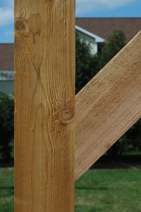
Things got complicated when he had to angle cut, though. The braces need 45 degree cuts on both ends, which because of the limitations of our saw required rotating the wood, angling the saw, and beveling the saw as well, several times on each end of each 5 foot brace. And yet, with a little patience and care, Nick was able to get all his cuts to fit like this.

Of all the photos we took of this project Nick likes this one most. He’s pretty proud of these cuts. He still recommends a 12” saw, though.

Setting braces 20

To set the braces Nick clamped each at the top, and then placed a couple clamps on the post just where the bottom of the brace would be placed. The brace rested on the bottom clamps, and were held fast by the top.

Here’s a photo of the setup, but here he was just determining fit. You can see that he’d angle cut the bottom of the brace, but the top still needed cutting. You can’t see the bottom clamps, but they’re there. Still hadn’t cut the notches for the cross halving joints at this point, as you can see. Once again, they’re easier to cut when the girders are on saw horses than mounted to posts.

Setting braces 1

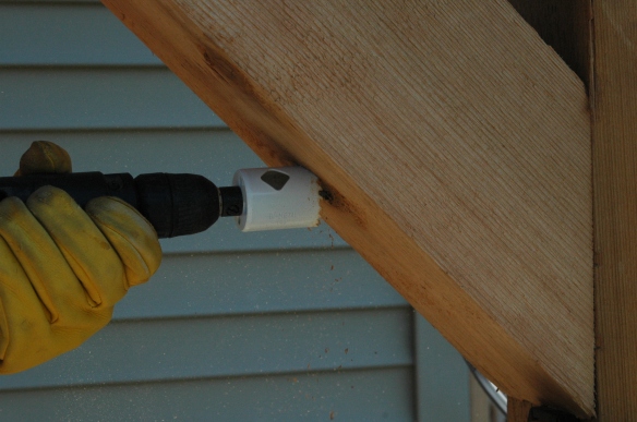
After both ends of the brace had been angle cut, Nick was ready to start drilling. Here Nick is using the hole saw to start the first bolt hole on the first brace he set.

Setting Braces 6

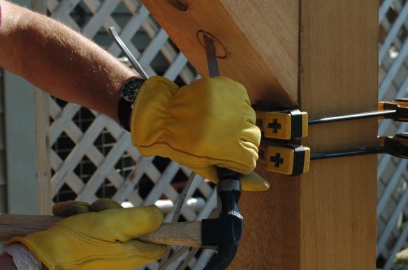
Next he chiseled out the hole. He’d already chiseled out the first hole, and here he’s working on the second. You can see how he used the clamps in this photo.

Setting braces 12

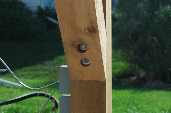
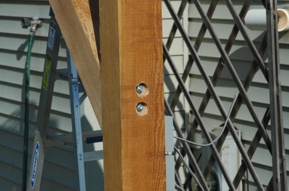
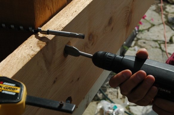
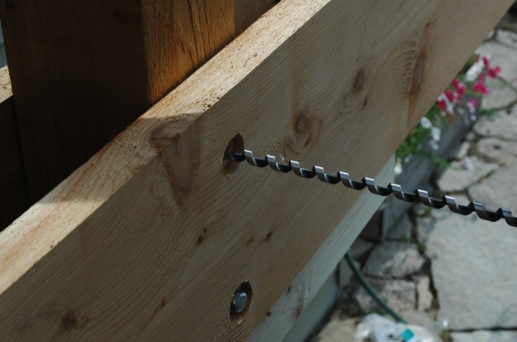
Next Nick used his 1 1/2″ spade to deepen the hole, then the auger bit to drill through, and finally the hole saw once again, and chisel on the post side of the hole, to recess the nut and washer. Here’s what the two ends of the bolt look like. You can also see that after being bolted the brace fits to the post precisely.

Setting braces 13

Setting braces 14

We used 10” bolts for the top hole and 8” bolts for the bottom. In retrospect Nick says he would have used a 12” on top and the 10” on bottom. The holes wouldn’t have needed to be as deep. Even still, there’s about 9 ¼” of wood being compressed between the top bolt head and the nut on the other side, and 7 ¼” for the bottom bolt, still a very strong joint.

Next, using a straightedge, a ruler, and a pencil, Nick determined where he wanted the bolts to pass through the upper part of the braces. They lie on the centerline of the brace, 3″ from the top and bottom. No real math involved. He just wanted the bolts far enough from the edge of the girder that the girder wouldn’t split if a gale was blowing, but not so close that the bolts would offer only limited resistance to a rocking motion.

Setting braces 15

Nick was really challenged angle cutting these braces precisely given the limitations of a too-small saw, but there was no way we were going to drop $300 for an average quality 12” compound miter saw we would only need for 16 cuts on this project (two 45 degree cuts per brace, two braces per corner, four corners).

A few notes about the following picture. You can see a bit of the knee brace above the near girder, behind hubby’s hand. This is because of the ¾” thick strip he cut off the top of the near girder, which will, when reattached, serve as the cover of the groove he cut for the light cable which will run from the second to the third light on the circuit. Though the groove only needed to be cut half way, Nick took the strip off entirely from the inside notch on one end to the inside notch on the other, not from outside to outside as he’d done on the first girder.

On the first girder, the cables emerged from the post between where the first pair of rafters would be located and the groove needed to be cut from where the reverse J cut led the cables out to the top of the girder. So a groove had to be cut between the rafters on the first girder, requiring a cap, hence the need to extend cutting the long strip all the way to the outside notches. Nick didn’t need to cut the 6” cap off the far end of the first wired girder. He realized only afterward that doing so was unnecessary.

On this side of the pergola the light cable would come into the girder from the third rafter, nearly two feet beyond the post, so there was no need to take off the caps at the ends of this girder. You can see it still attached, above the bolts. As with the second girder mounted on the first two posts, the second of these two girders did not require any special cutting besides the four cross halving joint notches.

Setting braces 17

At the end of our previous post we showed you a photograph of this girder with a really noticeable bow in it. After attaching the braces, here’s how it straightened out.

Setting girders 43

One thing concerned Nick about these braces. Well, actually only about one of them, the one he would attach later on to the two rafters that sandwiched the wired post. The bolts would pass through the post, but the fan and light cables run directly up the center of this post, exactly where the bolts would pass through. He wondered how it would look, with all bolts on the three other corners all on the center line, if he had to pass the bolts for this one rafter brace hard to one side to avoid the cables. Neither of us liked it conceptually, and we would have hated it in practice.

Then Nick remembered how useful lag screws are. The heads of the screws look just like the heads of the bolts, and they would still form a really sturdy connection. So he carefully measured how deeply he could drive his auger to remain shy of the cables, 1” deep in the far side of the post, wrapped his bit with masking tape at the depth he did not want to exceed, and using his hole saw, spade, chisel and hammer created the holes, then with his auger drilled away to the safe depth.

Setting braces 26

Here are a couple photographs of how the first four braces turned out. By the way, in the first photo you can see the long notch from the ¾” strip of wood Nick took off to cap the channel for the light cable.

Setting girders 45

If you look closely at the following photograph you can see the four ¾” notches cut for the cross halving joints with the rafters.

Setting girders 42


Next Post:  Preparing the Rafters

Patio Pergola Part IV: Setting the girders

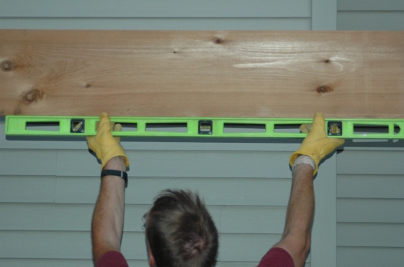
Because the girders were so heavy, Nick couldn’t rely on clamps to support them while he was preparing to drill the bolt holes through them and the posts, so he clamped some 2×4’s to the posts, leveled them, and screwed them in to create shelves on which the girders would rest, and then be clamped. Here Nick is leveling the first of two 2×4’s on the wired post before temporarily fastening them with deck screws.

Setting girders 1

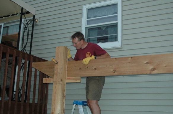
When we set the posts in the ground we ensured the tops were all level with each other. (See Post 1) Nick wanted the tops of the posts to be flush with the tops of the four rafters that would be sandwiching them later, so he had to ensure the tops of the 2×4 supports were all equidistant from the tops of the posts, 20” down. This distance represents the actual height of the girders, 11 ¾”, plus the actual height of the rafters, 9 ¾”, less the 1 ½” depth of the cross halving joints that we described in Post III. Here’s a photograph of how, after careful calculations, measurements, cutting, and mounting, the rafters do end up flush with the post top. It was taken after the slats had already been set.

DSC_1187

Here Nick is clamping the first girder, resting on its 2×4 support screwed to the second post.

Setting girders 3

Next he checked that the girder was level, and it was.

Setting girders 4

And here the first girder, clamped loosely to its posts, awaits the guiding of the light and fan cables through the reverse J channel described in the previous blog post.

Setting girders 2

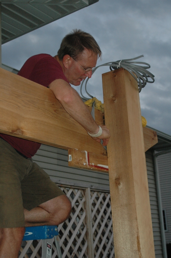
Here Nick is working the fan and light cables into the channel on the side of the girder. Once that was done he could clamp the first girder tightly against the post, set and clamp the second girder, and drill the bolt holes.

Wiring girder 2

After emerging from the post and running up the J channel routed in this girder, here are the cables for the lights and fan. They will be bent directly toward the camera, and then immediately to the right to lie in the channel cut along the top of the girder. The channel will later be covered by pieces of the ¾” strip Nick previously removed from this girder using the table saw. (Post III)

Wiring girder 3

Here Nick is setting another 2×4 support, ensuring that it is level in both horizontal directions.

Setting girders 5

Setting girders 6

Here both 2×4 supports are set and screwed to the posts, both 20” down from the post top, ready for the second girder. Nick removed the clamps after temporarily attaching the first girder to the posts with deck screws because he didn’t want to chance the clamps failing while he was working with the second girder and having the first one come crashing down.

Setting girders 8

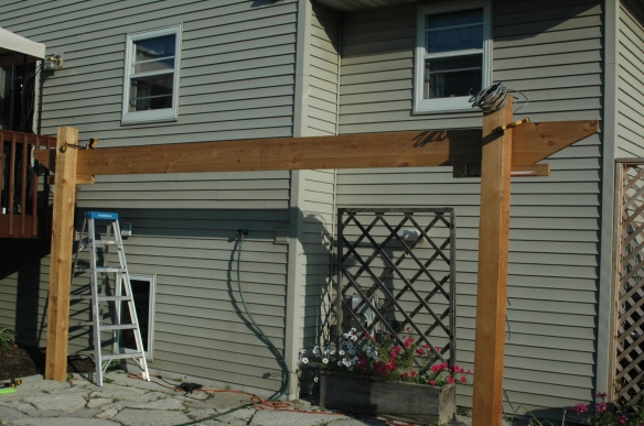
Here the second girder is mounted. The next step is boring the holes and bolting the girders tight.

Setting girders 10

We bought a slew of ½” diameter, 10” long galvanized bolts with a similar number of nuts, and double the washers, cleaning out three large building supply stores in the area of the bolts. Apparently these pieces of hardware aren’t in high demand. An employee at the first one Nick emptied told him it would be two and a half weeks until they’d get another supply of them. That’s when he went to the next two stores. Nick used three 10″ bolts per corner to attach girders and rafters, and three each per brace per corner, less one for which he substituted a lag screw which we’ll detail later, for a total of 35 10” bolts. We also used seven 8” galvanized bolts and one 8″ galvanized lag screw for the braces. Incredibly, the bolts, screws, washers, and nuts represented 10% of the total cost of this project.

Rather than getting a ½” spade to drill the holes Nick opted for an auger, which worked like nobody’s business, a really great tool. To drill the holes he first used a 1 ½” spade and drilled into the wood a bit. He didn’t want the bolt heads proud, but thought that having them sunk flush would be a nice touch. Then he used the auger bit to drill the hole through. For the first several holes in this project, he used the spade again to sink the washer and nut on the opposite side, but the point of the spade was narrower than the ½” diameter hole left by the auger, and the spade initially swung wildly as he was trying to drill, making a really rough hole. Thankfully, the four holes he finished this way were on the far side of the girders above, against the house, and unobserved.

When considering how to do a better job on the more visible holes Nick recalled the hole saw he’d used to wire the post, but that was a 1” and he needed a 1 ½”. Off to the hardware store. This was not the only time Nick ran off for a single item he discovered he needed mid-stream.  We will list all the tools we used in the final post.  That way, if we’ve inspired anyone to give a project like this a try we’ll save you a bunch of time and gas.

Here’s the process that evolved for drilling bolt holes. Using the 1 ½” spade, drill a hole about ½” deep. Using the ½” auger bit, drill through girders and post (and later, rafters and post). Then, with the 1 ½” hole saw, and using the through hole from the 1/2″ auger as a guide, drill from the backside about ½” into the wood, and using a hammer and chisel clean out the hole.

Setting girders 14

Setting girders 17

It’s unbelievable with all the photos we took of this project that we didn’t get one of Nick using the hole saw and chisel on the backside of the girders and rafters, but here’s one of how they’re used on the braces, which we’ll write about in the next post. By the way, since this photo is up, using the hole saw is the only way Nick could get a decent hole in the braces while beginning at a 45 degree angle.

Setting braces 2

As you can see from the first hole, above the one Nick is working on in the photo below, the saw and chisel combination gives a pretty clean hole.

Setting braces 10

Next comes driving the bolts through and cranking down on the nuts.

Setting girders 28

Here’s the first pair of girders completed, with the cables ready for setting in the long groove atop the back one.

Setting girders 33

We really think the recessed bolt heads and nuts looks nice, and there’s still a lot of wood left beneath the washers to make the corners really strong.

You’ll notice from this photograph and the one above that there are no notches for the cross halving joints on this girder. In his eagerness to get this piece up Nick forgot to cut them before the lift. No matter. He cut the four notches with the jigsaw after it was mounted. It’s easier to do on the saw horses, though.

Setting girders 34

The process for the second pair of girders was exactly the same. Here Nick is cranking down on the fasteners of the second pair.

Setting girders 40

This photo is a little dark, but you can see another example of a bowed girder, later straightened by the braces.

Setting girders 37

Next post:  Bracing the Girders..

Patio Pergola Part II

Here’s the list of the cedar lumber, hardware, and electrical items we bought to build this project:

Wood
4    6″ x 6″ x 12′ for the posts
4    6″ x 6″ x 10′ for the braces
4    2″ x 12″ x 20′ for the girders
14  2″ x 10″ x 18′ for the rafters
14  2″ x 6″ x 20′ for the stringers

With the 7% contractor’s discount the lumberyard generously extended us, the wood cost about $2,700.

Galvanized hardware
35  10″ x 1/2″ lag bolts
7     8″ x 1/2″ lag bolts
1    10″ x 1/2″ lag screw
1      8″ x 1/2″ lag screw
44  nuts
88  washers

Just this hardware alone cost about $500.

Electrical items
1  wet-rated ceiling fan
6  exterior can lights
2  decorative adjustable light switches
1  GFI receptacle
3  exterior electrical boxes
3  box extensions
3  box lids
6  flood lights
100′ of UF cable
a bunch of cable nuts

We got the fan on sale for $129, the lights cost $240, the bulbs were $75, and the rest totaled around $100.

Here’s a photo of the cedar lumber we bought for the pergola after it was delivered and stacked in the garage.  This photo doesn’t include the four posts that we’d already planted around the patio.
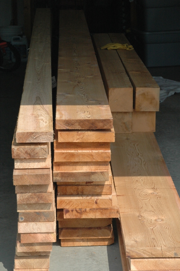
stack of wood

The four boards on the lower left are the girders.  They are twenty feet long and rough sawn to 1 ¾ x 11 ¾ and weighed each about 100 pounds.  The 6 x 6 posts on top of them are ten feet long, but will be cut into five foot lengths.  The eight sections will become the knee braces at each pergola corner.  When cut they probably weighed about 45 pounds each.  The fourteen boards in the middle will become the rafters.  They are eighteen feet long and rough sawn to 1 ¾ x 9 ¾ and weighed about 75 pounds apiece.  The fourteen boards on the left are twenty foot lengths of 1 ¾ x 5 ¾ weighing about 45 pounds apiece.  They will become the slats that overlay the rafters.  The twelve foot 6 x 6 posts I’d already placed in the ground weighed about 110 pounds each, except for one which seemed drier than the other three and weighed maybe 100 pounds.

When planning the pergola, we decided we wanted to run electricity throughout to make it more functional for longer periods of the day.  Nick wanted to conceal the electrical wiring somehow to give the whole structure a more polished look.

Most examples he looked at that were wired for electricity had cable run through metal or PVC conduit attached to the wood.  Some builders forewent the conduit entirely and simply attached their cable to the top, sides, or undersides of their rafters or slats with cable staples.  These examples probably were wired after their original construction, as an afterthought.  But, as our bedroom overlooks the site of the pergola, he just didn’t want to look down on all his effort to see a bunch of exposed wires or conduit.  He was looking for a more elegant way, and knew it had to be part of the plan from the start.

During his research he came across an article suggesting routing a channel along a post and running wire though the wood a couple of feet for a receptacle, concealing the wire and channel with a strip of wood cut to fit snugly.  He extrapolated that idea to the entire pergola, and began planning how it could be done.

He started with the post which was going in the ground nearest where electricity runs into the house.

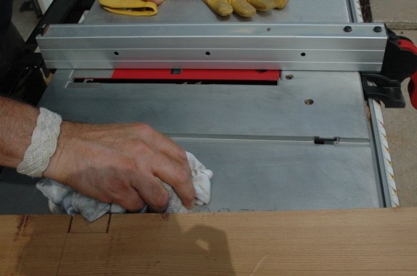
Before beginning the cuts, Nick applied a coating of car wax to make the table surface on the table saw more slippery so that the heavy pieces he would be cutting would slide more easily across.
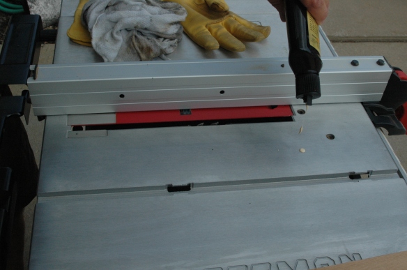
Setup for post, girder, rafter cuts 11

Setup for post, girder, rafter cuts 12

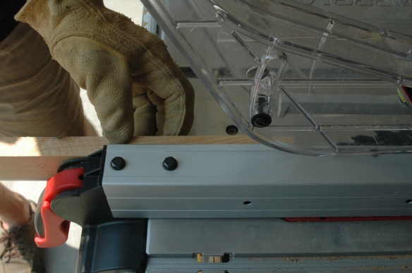
He removed the safety gadgets from the saw.  They would prevent the timbers from passing fully over the blade.  (The rollers you see below were an indispensible tool.)
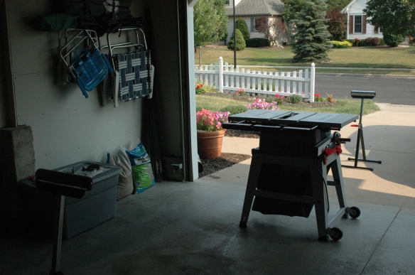
Setup for post, girder, rafter cuts 1

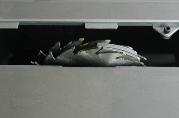
Then he removed the blade and replaced it with ¾” of dado blades.
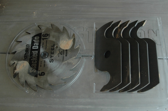
Setup for post, girder, rafter cuts 5

Here are the dado blades installed.

Setup for post, girder, rafter cuts 3

The channel would be cut in the shape of a T, with the deepest part of the cut, where the wires would be placed, being the first pass, and centered on the post.  He began the cut at the very bottom of the post.
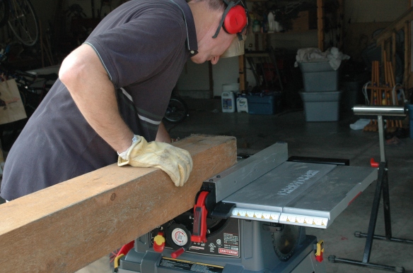
Wired post 20

It’s important to align the post with the fence (the guide with the red handle, above), and to ensure the roller supports are perpendicular to the piece being cut so that the wood doesn’t gradually drift out of true and the cut become skewed.  Nick checked often during each cut that his work was still flush with the fence, and moved his roller supports several times as the piece was slid along the table, adjusting the height of the supports as needed to keep the post moving along the entire table surface.

Here is the beginning of the very first cut.
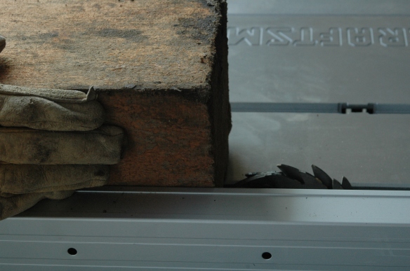
Wired post 19

Adjusting the height of the rollers ensures an even distribution of the weight of the wood over three points (the table surface and the two rollers) and makes pushing the heavy work over the blade easier, and safer.
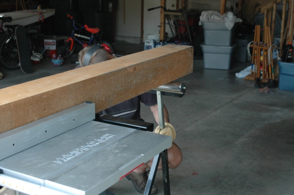
Wired post 22

He didn’t extend the cut all the way to the top of the post, but only to a point where the terminus of the cut will be concealed by a girder.

Getting ahead of myself, here is a photo of the girder on the side of the post where the wiring is located.  The first pair of rafters is also set, but that happens even later.  As you can see, the cut on the post cannot be seen because it ends below the top of the girder.  I’ll explain the purpose of the “cap” on top of the girder later.  You can see a seam just above the bolt.
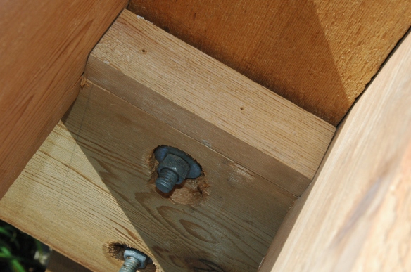
DSC_0952

Here is what the post looks like after the first pass.
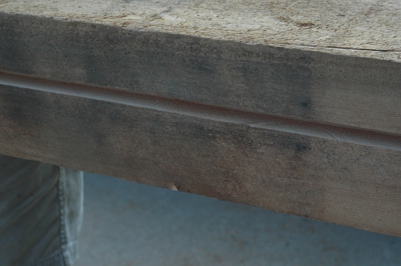
Wired post 26

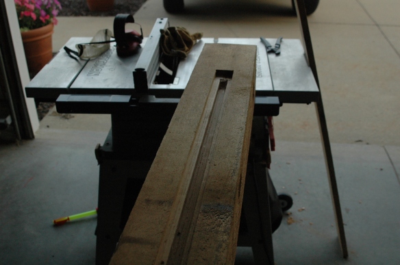
Nick then set the post up as before, moving the fence about ½ inch to create the first half of the top of the T, then moving the fence again for the third pass to complete the T.  Here’s what that looks like.
Wired post 25

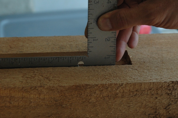
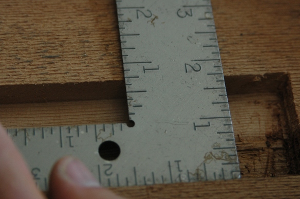
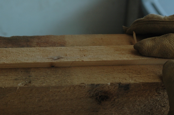
He used a hammer and chisel to square the end of the cut up nicely.  Even though the cut would be concealed by a girder, Nick wanted the end of the cut square so that the strip he placed over the entire cut to enclose the wire would fit snugly at the top which, with a little silicone caulk, would prevent rainwater from running down the channel.

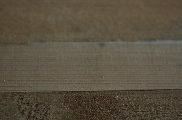
The dimensions of the cut were 1” deep and ¾” wide at the bottom of the T, ½” deep for the cross part of the T, and 1 ¾” across the top of the T.
Wired post 38

Wired post 39

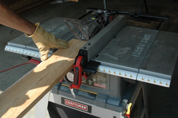
Next, having replaced the dado blades with the table saw blade, he reattached the safety attachments to the saw and began cutting what would be the cover of the groove, first ripping it for width,
Wired post 11

then for depth.

Wired post 14

Then he dry-fitted the cover to ensure it was snug.
Wired post 30

Wired post 8

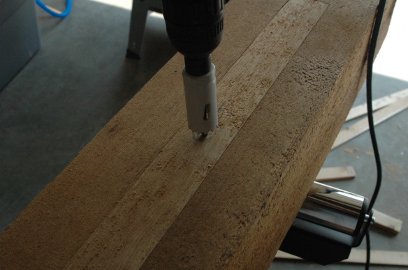
Next he determined where he wanted the wires for the receptacle and switches to protrude from the post, marked the locations, and used a 1” hole saw to take care of business.  The hole he’s drilling here is the one at the top of the post, where the fan and light cables will emerge.  The cover is not yet attached.
Wired post 16

Wired post 27

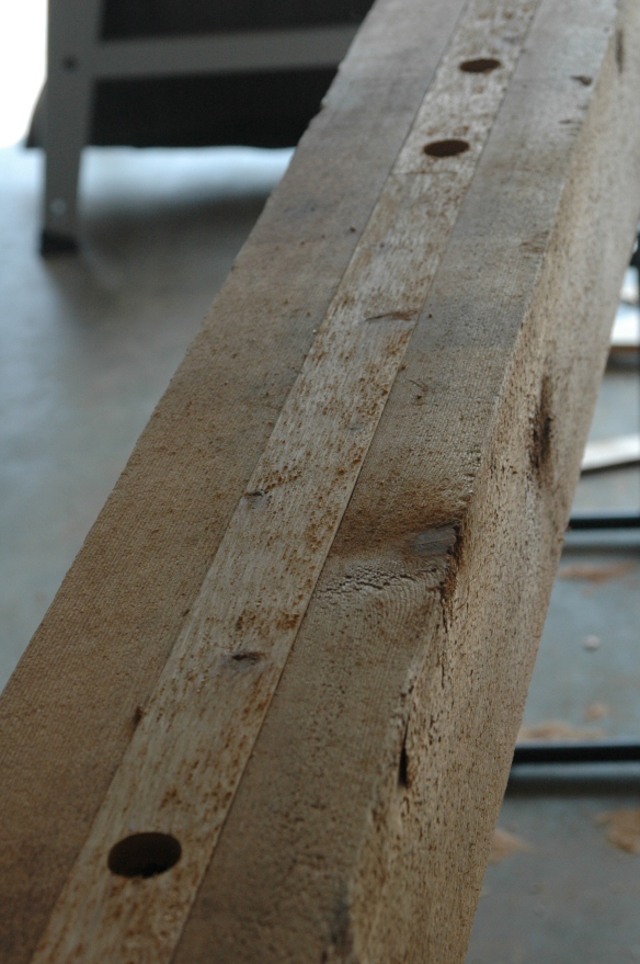
Here’s what the lower three of the four holes look like when done.  The bottom one is for the receptacle, and the middle two are for the fan and light switches.
Wired post 29

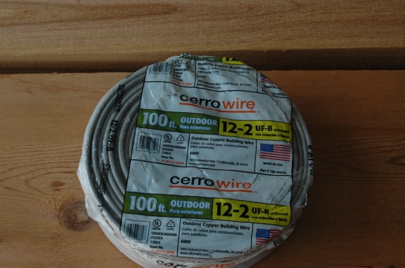
Next he removed the cover and began laying wire.  He used UF 12-2, pretty heavy gauge stuff, and designed to be buried.  That’s what the UF means, underground feed.  The cover is really sturdy, and a pain to strip.  He could have used thinner gauge wire, but he had nightmares of having to disassemble the entire pergola if he had and something snapped while he was working it through a bunch of 90 degree bends.  Better safe than sorry.

Here’s what the UF wire looks like.  It’s got a very tough grey cover, impervious to the elements.
Wired post 46

We bought this wire cutting and stripping tool several years ago when he finished our basement.  It’s very handy.
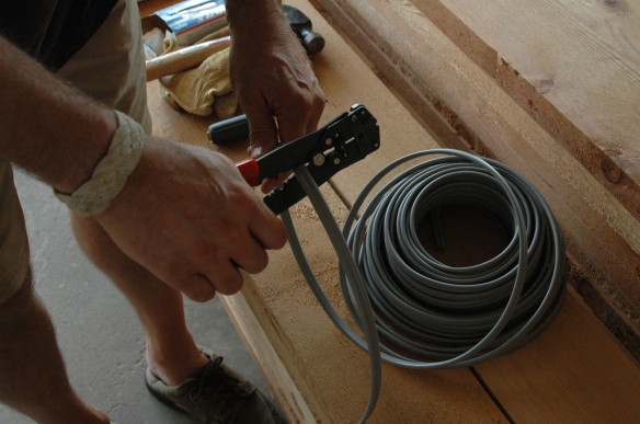
Wired post 15

From the bottom of the post he ran up the single cable which would bring power from the house, and fed it through the receptacle hole.
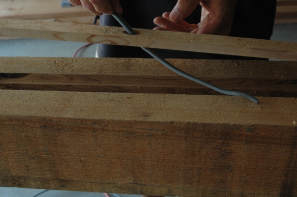
Wired post 31

From that hole he then fed two wires and laid them further up the groove to the two switch holes.
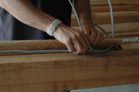
Wired post 32

Lastly, he fed one cable each from the switch holes and continued them up the groove to the fourth hole he drilled near the top.  Here’s what that looked like after he’d run the first of these two cables.
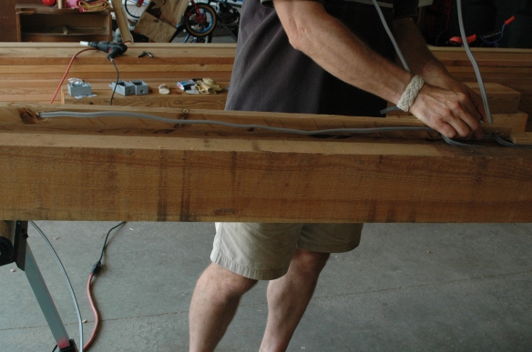
Wired post 33

Then Nick laid down a bead of silicone caulk on both sides and the very top of the cut, near the top of the post,
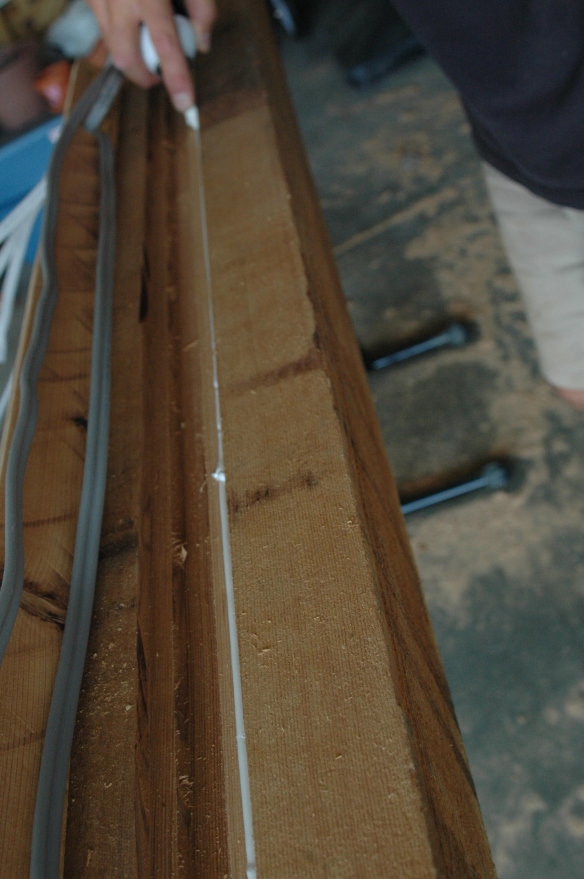
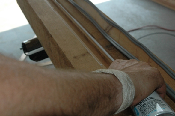
Wired post 42

Wired post 43

and reinserted the cover into the channel, very carefully nailing the cover down with finishing nails, angling the nails away from the wire to minimize the possibility that he might nick one.
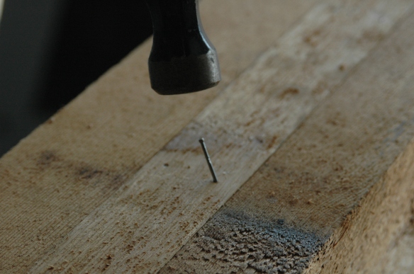
Wired post 5

He didn’t think to use galvanized finishing nails, which isn’t a big deal, but still a regret , because after we’d set this post in the ground, the first rain it was exposed to caused the nail heads to begin discoloring the cedar below them in streaks.  Thankfully the wired side of the post faces the house and it’s not really noticeable, but the post looks like it’s got two dozen tiny little eyes, all with running mascara.  Nick made sure that every bit of hardware from then on was galvanized.
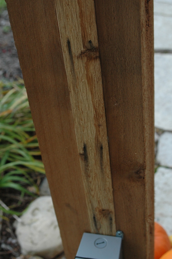
DSC_1210

He left about fifteen feet of cable leading from the receptacle, which was used to connect the pergola to the breaker box in the basement.  Here it’s resting on a board that’s not a part of this project.
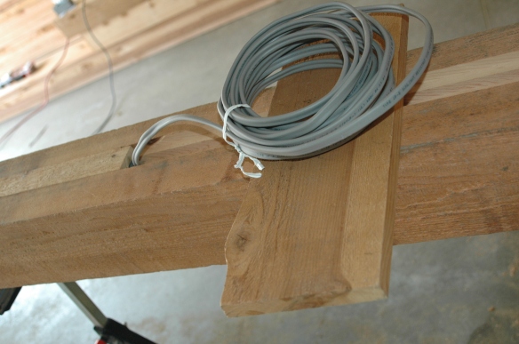
Wired post 36

There were five feet extra after it was connected, but that’s a good thing.  Cable is cheap, but rewiring the post if he came up short would have been a major headache.

Here’s what the post looks like after these steps.  The wires on the right will be in the receptacle box.  The cables coming out of the post near the center are for the light and fan switches, and the cables emerging at the left are for the lights and fan themselves.  He left about ten feet to reach the first light, and about twenty for the fan.
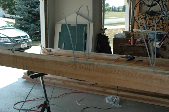
Wired post 1

Next he placed a thick bead of caulk around the holes for the receptacle and two switches to seal the holes against the elements,
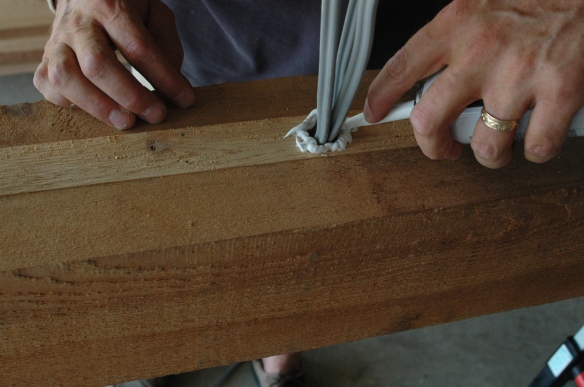
Wired post 45

and placed the outlet boxes in position, pressing them against the caulk and screwing them down.  Here’s the receptacle box.  The two switch boxes are just like it.  He drilled a weep hole on the bottom of these boxes to prevent rainwater from collecting inside them.
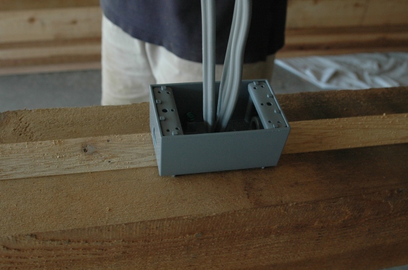
Wired post 4

Voila!  Post done!  Next step, sticking it in the ground.
Patio Pergola Part I

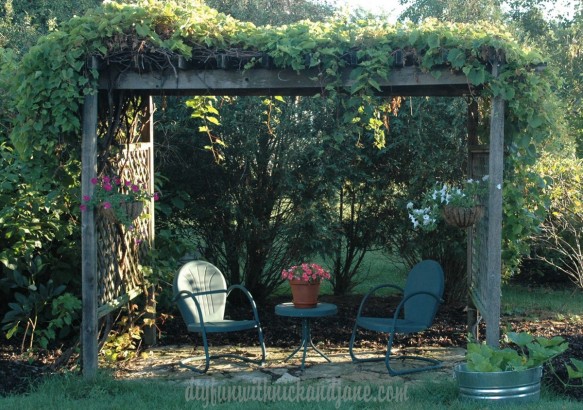
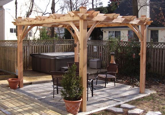
When we first moved into our house sixteen years ago it was a new neighborhood and there were absolutely no trees in our yard to provide us with shade.  We had three kids and, of course, they loved to play in the back yard.  To make spending time out there during the summer more bearable, Nick and I decided that we should build a small pergola and train grapevines up it for fast growing shade.  The trees have grown quite a bit since then but we still enjoy sitting out under our first diy project.Pergola morning sun We would love to eat dinner under the shade of our pergola, but fitting a table that accomodates seven (our family has grown slightly) is a bit problematic.  We laid a fairly large flagstone patio right next to the house where we have a table, chairs and umbrella. Unfortunately the heat can be pretty intense at dinner time and the umbrella doesn’t do a good job of protecting us from the late day sun. After a lot of internet searching we’ve decided to build one that’s a combination of this…

Patio Pergola Idea

and this.

Pinterest pergola

We want our pergola to cover most of our patio so we’ve decided on building a 16′ x 14′ structure. It will also be wired for an outdoor ceiling fan and lights. We scored some bricks salvaged from an old 1800’s schoolhouse that burned down and eventually we will add a fireplace to the dining area.

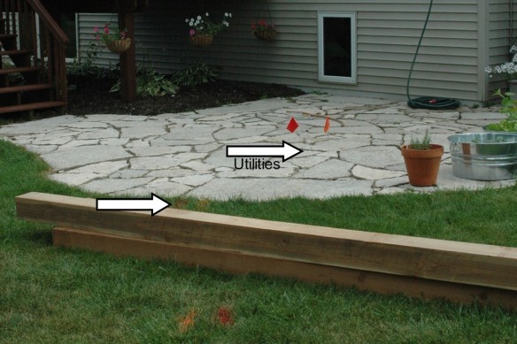
But first things first. We contacted Diggers Hotline before we started anything. We’ve had our utility lines marked out for past projects but we always err on the side of caution so we gave them a ring and in a few days a representative from the utilty companies arrived. We asked that spray paint be used only on the grass and to please use flags over hardscaped and mulched areas. They were very accomodating.
Digger's hotline markings

When he finished we were surprised where our lines were located. Our memories had them placed much farther to the right of our patio. The path they took was definately not a straight line from the utility box at the corner of our lot. Sadly, they go right through where we had planned on putting the fireplace. As a result we’ve had to reconfigure where that will eventually go.

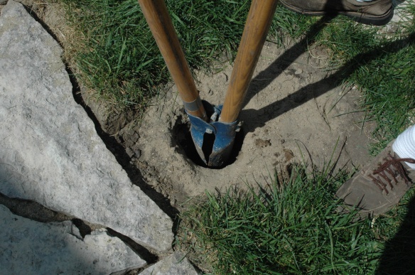
Next we researched what our frost line is. To prevent heaving we needed to dig holes that went further down than 42 inches. We (I mean, Nick) dug holes that were 4 feet deep. This is what he did for our first pergola and we’ve had absolutely no problems.

DIGGING THE POSTS

First, a little disclaimer.  The photos that we took below of digging and placing the posts were taken over the course of doing the first two. So while it looks like we’re digging the hole for the first post in our grass, this was actually photographed while digging the hole for the second post.  We placed the first post right next to our house and needed to remove a stone from the patio to do so. It really doesn’t change the process of digging and placing posts, we just took a little poetic license with our pictures.

DSC_0949

We plotted where our posts needed to go and started digging. Nick learned the hard way that it’s best to dig a hole quite a bit wider than the width of our posts so as to have some wiggle room when it comes time to align one post with the next.  He did not initially do this and he wound up having to remove a post and dig the hole wider.     TIP:  We found that if removing stones from a hole is necessary, a shop vac works rather nicely. It was tedious work but it’s so important to have those posts aligned properly.

ADDING THE STONE

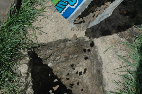
After the hole was dug, we added a few inches of river gravel to the bottom.Adding stones to hole

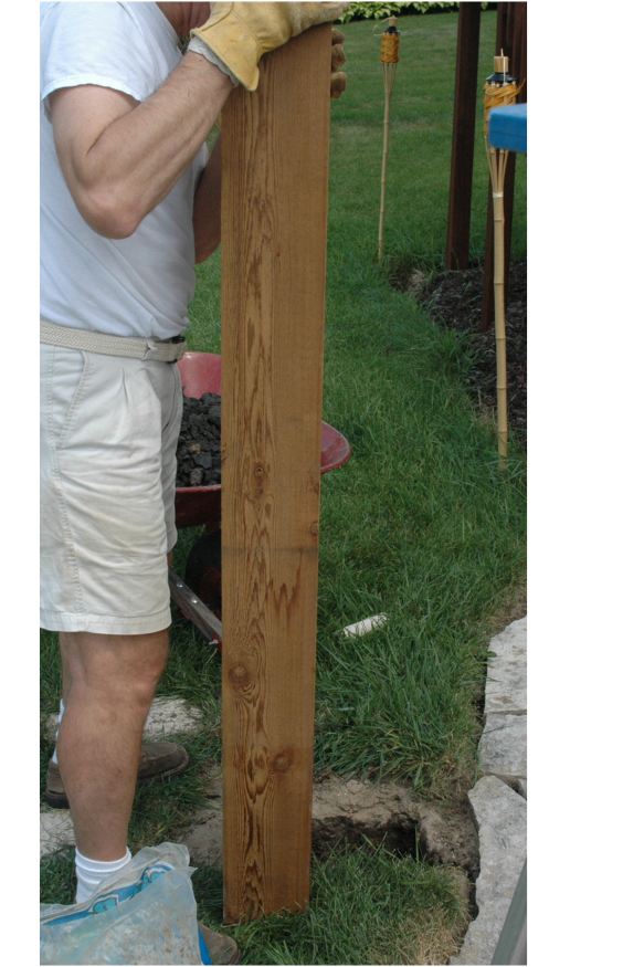
Nick then dropped the post in and moved it around a bit to tamp down the rocks.Project2

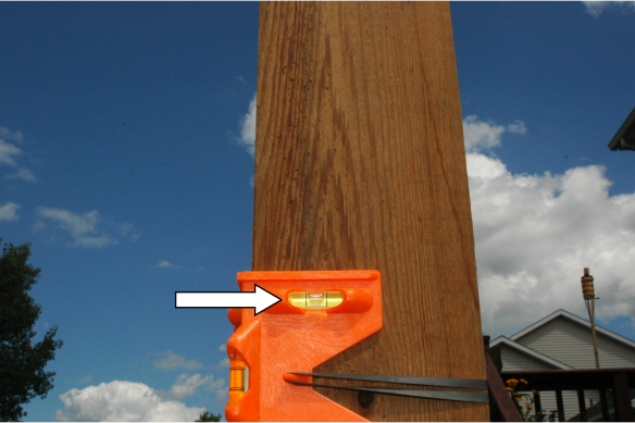
We then used a post level to check that the post was true before adding more stones.Level with arrow

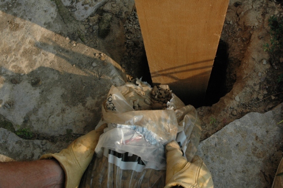
pouring rock 2

Then he wiggled it around some more checking the level frequently to see that the post remained true. Project2

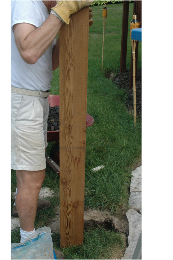
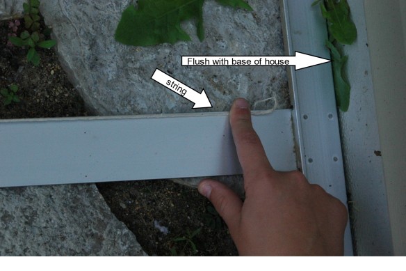
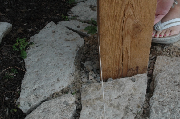
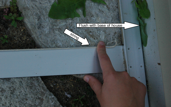
We added a little more rock, wiggled it a bit to settle the stones and then checked to see that the post was also true to the house by using a drywall square lined up to the foundation of the house and a string. We lined up the string with the square….string check

and passed the string along the outside of the post . We made any adjustments to the post necessary to make it flush with the string.  We then added more rock, adjusted etc. until the hole was filled and the post was true.DSC_0943

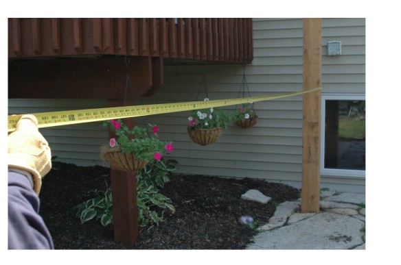
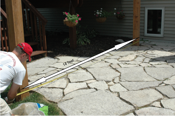
Next we measured 14 feet to where we would place the second post.

Measuring post distance

We placed a 6×6 square piece of cardboard where the new hole was to be dug and started on the next post.  After we lowered the second post into the hole we repeated the stones, wiggle, measure steps all over again.

re-check post distance

 14 feet from outside edge of Post #1 to outside edge of Post #2.

Patio Pergola

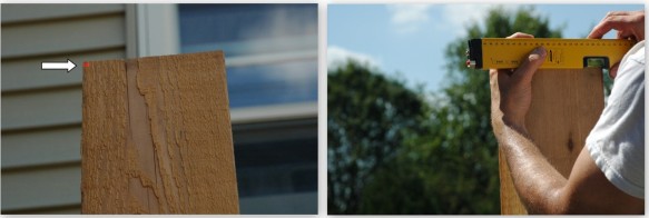
Using a laser level we checked to see that it was exactly the same height as the first post.

Using the drywall square and the string, we checked that the first and second posts were true to each other.

String checkThis time we ran the string, flush, along the inside of the first post and continued it past the inside of the second post. Making sure that it was flush on both posts.

Patio Pergola1

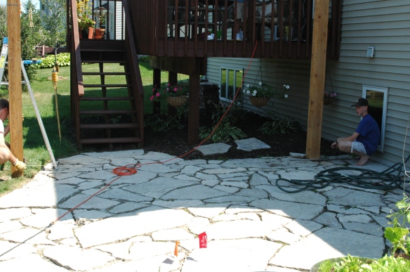
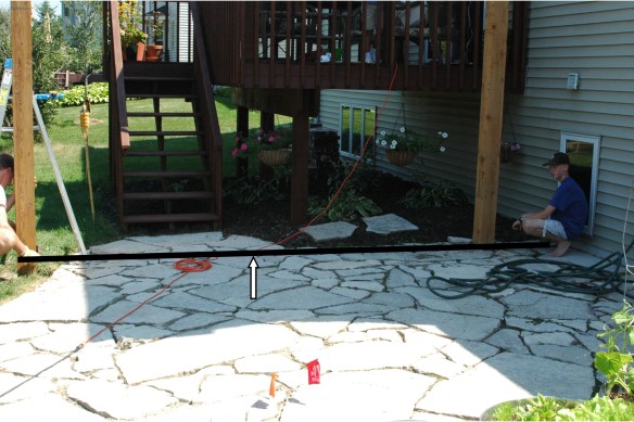
Here our son, Luke, is the official string holder. The string doesn’t show up well in this photo so I’ve added one where I highlighted the line that the string takes.DSC_0976

You’ll notice that the string does not lay flat across the ground the entire way. That’s because the slope of the patio falls away from the house and we wanted the string to be level and not follow the slope.

Computer enhanced string

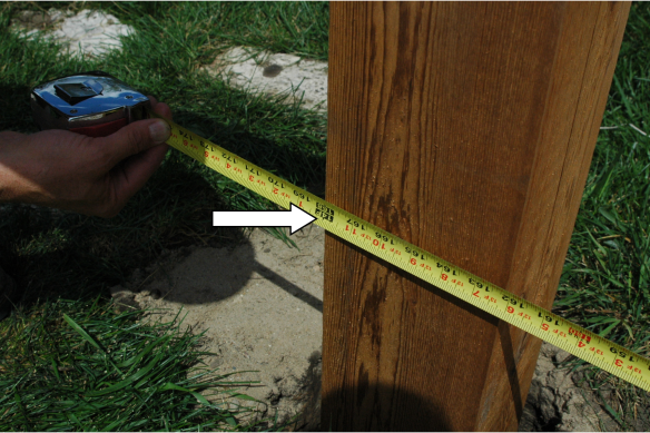
Checking once again to make sure that we have the posts 14 feet apart from outside edge to outside edge.Post with 14 ft. arrow marking

Exactly 14 feet and true to both the house and Post #1. Yea! Two posts down, two more to go.

_______________________________________________________________________

The next important measurement ensures that the whole configuration is square.

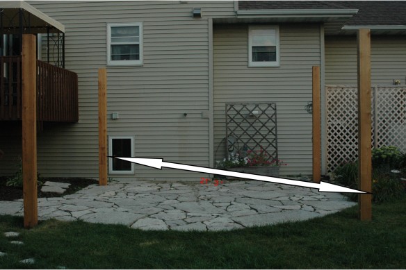
Using the Pythagorean theorum and knowing that we had 2 sides of 16 feet and 14 feet, we calculated the diagonal to be approximately 21′  3 1/4″.  (This measurement is approximate because the actual answer was just slightly over 21.25′. )

21′ 3″ from post 1 to post 3

Diagonal post msmt

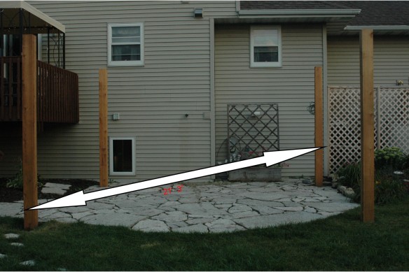
21′ 3″ from post 2  to post 4 Diagonal post msmt 2

Before finishing each post, we repeated all the previous steps to ensure trueness of each post to the house and to each other.

The most tedious part of the pergola is now done!

So until we get finished with Part II, I’ll leave you with some images of other beautiful pergolas that we found while gathering ideas for ours.

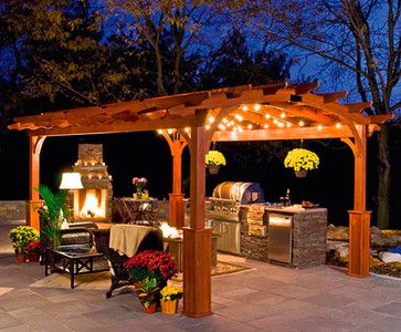
Pergola with fireplace

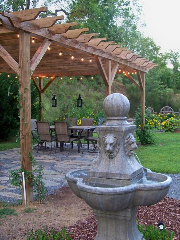
Pergola with string lights

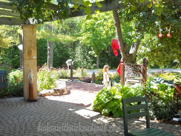
Door County pergola 1

Thanks for stopping by!